Appearance
Tutorial #2a: Calculating A Simple Tree with HydraCALC Sizer
The system you will be calculating is shown below. In this system, 3'- 0" drops are being added at the sprinklers.
Open the HydraCALC V50 program. For this example, you will use HydraCALC Sizer to build the system.
Select HydraCALC Sizer from the View Menu. The HydraCALC Sizer program will open.
Select the Tree and Psi radio buttons.
Set up the layout with the System Info dialog box shown here.
Enter the name as Tutorial 2. The System Type will be Wet. The Remote Area shape will be 1.2 and the size will be 1500 ft^2. Enter -25 feet to the System Riser Connection (ASR). There will be 4 Lines, 10 feet apart. There will be 7 heads per line, 12 feet apart. The Riser Nipples will have a Tee at the top and will be 3 feet long.

When you have this, press the Refresh Drawing button to update the graphic information. Use the Arrow buttons at the bottom of the screen to move the main to the correct position with two heads to the right.
Set the branch lines sizes by picking them with the mouse. The last two pipes are 1inch diameter. The next two are 1 1/4. The pipe next to the riser nipple is 1 1/2. All branch pipes are Schedule 40. The riser nipples are 2-inch Schedule 40. The cross main is 3*-inch* Schedule 10.
Press the City Supply Test Point button to add a water source and underground pipe.
Pick the hydrant with your mouse to open the Test Hydrant Attributes dialog box.
Enter the water supply data as shown here. A 250 GPM hose allowance is added as well. Press OK to close the box.
Pick the Underground Pipe in the graphic. This will open the System Feed Attributes dialog box.
It is here where you specify the pipe from the supply to the cross main. The top row is for the feed main. Enter a length of 15 feet. It will be 4-inch Schedule 10. You can right click to select the Pipe Type. Add an E for the 90 degree elbow at the top of the system riser. The C-Factor is 120.
The second row is for the system riser. It will also be 4-inch Schedule 10. Add an Avk for an alarm valve, G for a gate valve, an E for a 90 degree elbow and a fixed pressure loss of 5 PSI. The C-Factor will be 120.
The third row is for the underground from the bottom of the system riser to the test hydrant. It will be 8-inch, class 52, cement lined ductile iron. Right click, select CL52CLDI from the list of pipe types. The length will be 250 feet. Add an E for a 90 degree elbow. The C-Factor will be 140. Press OK to exit when you have finished the entries.
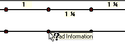
All your active heads will be colored red. If you hover your mouse over them, the tool tip Head Information will appear. Pick on one to set the head criteria. The Head Attributes dialog box will appear.
Set the K-Factor to 5.6, the Density to 0.15, the minimum pressure to 7 PSI and the elevation to 20 feet. The drop length will be 3 feet. Press OK to exit. Now is a good time to save your file.
Your setup is complete. You are now ready to run a calculation.
Press the Calculate Results button to start the calc. A dialog box will appear showing your pressure usage.
The color-coded bar graph makes it easy to see where most of the pressure loss is taken up. In this example, most of the pressure loss occurs along the branch lines. At this point you could begin changing pipe sizes and recalculating until you get an acceptable safety margin. In this example, the safety margin will be considered acceptable. Press OK to exit.