Appearance
Tutorial #4: Calculating a Standpipe System with A Pump and A City Supply
The system you will be calculating is shown below.
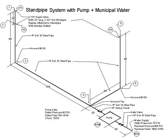
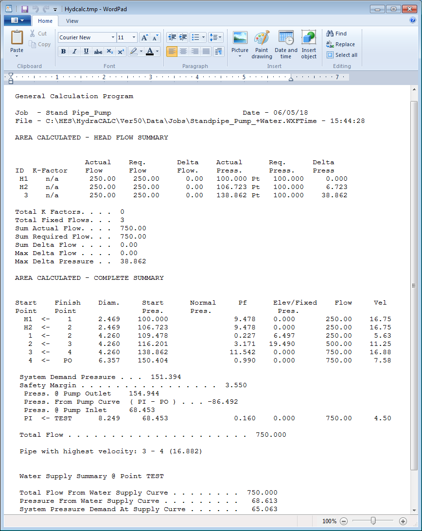
This standpipe system has a pump that is fed by a city supply. The method used here can also be applied to booster pumps supplying water to sprinkler systems. Here is what the HydraCALC screen should look like:
The easiest way to get this is to Save AS the file from the previous tutorial and modify it so that it appears as shown here. Note that PI to TEST is the pipe that feeds the pump inlet from the test connection. Press the Water Source button at the top of the screen.
From the Edit Water Supplies dialog box, select Supply 1 and delete any current entry. Press the Edit City button.
Enter the city water supply data as shown here. Press OK to exit. You will return to the Edit Water Supplies dialog box.
Enter TEST as the Connection for Supply 1. Select Supply 2 and then press the Edit Pump button.
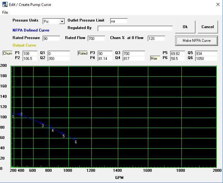
Enter a Rated Pressure of 90 PSI, Rated Flow of 700 GPM and a Churn Percentage of 120%. Press the Make NFPA Curve button. This will calculate pump curve coordinates and place them in the cells of the Output Curve. Press OK to exit.
You will return to the Edit Water Supplies dialog box.
Enter the data as shown here. Note that this time the Pump Inlet, Pump Outlet and Connection all have different labels. This is in contrast to all of the labels being the same as they were in the previous tutorial. This is because the pump is being fed by a city supply. When you have this setup, press the OK button to close the Edit Water Supplies dialog box.
Press the Calculate button. The Pre-Calc Questions dialog box will appear.
Set up the box as shown here. Hose valve H1 will be the Remote Point and TEST will be the Source Point.
Press OK to start the calculation. The Hydraulic Calculation dialog box will appear when the calculation is complete.
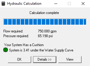
When you press the View button, a detailed report will appear. You will find that hose valve H1 is most remote with a flow of 250 GPM at a pressure of 100 PSI. H2 and H3 will have higher pressures. The flow demand is the same as what is required for the previous tutorial because the systems are identical except for the addition of a city supply in this example. The pressure demand is less here because of the pressure added by the booster pump.