Appearance
Tutorial #1a: Simple Tree Project
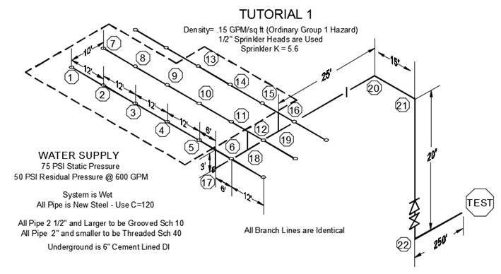
The system you will be calculating is shown below. This tutorial may be completed with a non-licensed, trial version of HydraCALC.
Start HydraCALC V50 and save a new file as Tutorial1.wx1. HydraCALC files have the WX? extension. The last character will be the letter F unless a number is entered. A number can be used to identify a remote area. For example, WX1 could be used for remote area 1, WX2 for remote area 2, and so on.
Fill in the header cells as shown. Enter a Project Name of Tutorial 1 and the date. The common elevation will be 23 since most of the nodes in the system including the heads are at 23 -0 .
It doesn t matter where in the system you start entering information however you should use a logical order so that it will be easier to interpret your data. This example will start with the branch lines.
Enter the data for Node 1 and the pipe between nodes 1 and 2.
Pick the Node 1 cell and enter a 1 with the keyboard. Press the Enter key and the cursor will move to the right.
The cursor movement is controlled by the Input Direction button at the top of the screen. Enter 2 in the Node 2 cell and press Enter. You will arrive at the Dia or Diameter cell. Right click your mouse.
The Pipe Input dialog box will appear. You have the option of using Actual Diameters or Nominal Diameters.
If you use Nominal Diameters, you must specify the Pipe Type in the calculation screen. If you use Actual Diameters, you do not have to specify the Pipe Type in the calculation screen. For this example, Nominal Diameters will be used.
Select the Insert Nominal Diameters radio button. Highlight the 1 pipe size on the left and the SCHED-40 pipe type on the right. Press OK.
You will return to the calc screen with the nominal diameter of the pipe entered. Press Enter again to move to the Pipe Type cell. This was entered automatically.
Press Enter again to move to the Len or Length cell. Enter 12 and press Enter for twelve feet. Pipe lengths are entered in decimal feet. There are no fittings required so press Enter again to move to the C Fact. or C-Factor cell. You can right click to select or type in 120 and press Enter.
The Input Type organizes pipes so that the Search and Replace function can be used to make global replacements. For example, you may want to identify all your mains so that the size could be changed easily from 3 to 4 diameter. This is accomplished using a common Input Type.
For this pipe, right click and select Ln-S for a Straight Feed line. Press Enter to move to the Num. Hds. or Number of Heads cell. This cell is filled when importing system data from HydraCAD. It tallies the number of heads along the path. You could enter this data manually; however, it is not necessary for performing hydraulic calculations.
Press Enter to move to the K / Flow cell.
The K / Flow cell is used to identify flowing heads and hose flows. Enter 5.6 for the sprinkler K-Factor and press Enter.
Enter a Density of .15 and an Area of 120 for 120 square feet. In the Pressure cell, enter 7. HydraCALC will use the pressure calculated from the density, coverage and flow, or the pressure entered in this cell; whichever is greater. This ensures that the minimum pressure required by code or the manufacturer's specifications is met.
Press Enter to move to the Elev. or Elevation cell. Since Node 1 is at the Common Elevation of 23 -0 , the elevation does not have to be entered here. HydraCALC will assume that the node has the Common Elevation if the elevation cell is blank. Press Enter to move to the next row.
You are now going to enter the data for Node 2 and the pipe leading to Node 3. Press Enter twice. Note that the node numbers are incremented and entered automatically. Press Enter again.
This time note that the value from the cell above is duplicated. This feature helps to save time when entering data. Keep pressing the Enter key until the second row is completed and you are starting the third row.
Press Enter twice to input the node numbers 3 and 4. In the Diameter cell right click, select *1 * and Schedule 40 and press OK.
Keep pressing Enter until the third row is completed and the fourth row is started.
Press Enter twice to input the node numbers 4 and 5. Continue pressing Enter until the fourth row is completed and you are ready to start the fifth row. Press Enter twice to input the node numbers 5 and 6. The diameter is for 1 Schedule 40 steel pipe. This pipe leads to the top of the riser nipple. Enter 6 as the length and press Enter to move to the Fittings cell. Right click your mouse to open the Fitting Input dialog box.
This dialog box is used to enter equivalent lengths or fixed pressure losses. Pick the NFPA 90 Flow Thru Tee from the list on the right. A T will appear in the Fittings cell. You can enter as many fittings as you would like however all that is required now is the single tee at the top of the riser nipple. Press OK to exit.
Press Enter until you reach the next line. Now, you will move down the riser nipple to the main. Press Enter once to enter the node number 6. Enter 17 as the second node number. This is the point where the riser nipple meets the main as shown in the drawing.
Right click over the Diameter cell and select a 2 Schedule 40 pipe size. Press OK to exit.
The pipe length will be 3 feet. Enter the 1T in the Fitting cell.
Press Enter until you reach the Input Type cell. This time, right click and select Rn-S for a riser nipple. Continue to press Enter until you reach the start of the seventh row.
This completes the first branch line. You may want to put notes into your data to help with organization. First, you have to move the current data down one row.

Move the cursor to the first row of data and press the Insert Line button. A blank row will be inserted.
Now, you can use this row for a note. Any data that is preceded with an asterisk (***) is ignored by the calculation program. Move the cursor to the beginning of row one and enter *BRANCH LINE 1.
Move the cursor to the beginning of row eight. Enter the note BRANCH LINE 2. Highlight rows 2 to 7 with the mouse.
Press the Copy button.
Move the cursor to row 9 and press the Paste button.
The branch line data that was placed on the clipboard is pasted below the BRANCH LINE 2 note. Now, all you have to do is to change the node numbers because the branch lines are identical.
Change the node numbers to what is shown here which should agree with the system drawing.
Move down to row fifteen and enter the note BRANCH LINE 3. This branch line has only three operating sprinklers. See the system drawing.
Highlight the last four rows of Branch Line 2 and press the Copy button. Move the cursor to row sixteen and select Paste.
Change the Branch Line 3 node numbers to what is shown here to agree with the system drawing. This completes the branch lines.