Appearance
Tutorial #2b: HydraCALC Sizer data to HydraCALC
You now need to save this information in a format that can be read by HydraCALC. The calculations obtained through HydraCALC Sizer are for estimating only. Calculations for approval must be performed in HydraCALC V50.

Press the Build Hydraulic Input & Exit button. The Save As... dialog box will appear.
Enter the filename as Tutorial2.wx1 and press the Save button. HydraCALC Sizer will close, and you will return to HydraCALC V50.
The data will now appear in HydraCALC.
Enter a Project Name and Project Date. The Common Elevation value will be 20 feet which is the elevation of the heads on the drops. Note that HydraCALC has automatically added nodes as indicated in the drawing on the first page of this tutorial. Correct diameters have been entered for the specified nominal sizes and pipe types. Pipe lengths have been entered in feet along with attached fittings.
Note the values entered in the K/Flow column. The =EQ1 relates to the equivalent length calculation in the Equivalent K Piping tab. The equivalent length takes the sprinkler, drop pipe and fittings into consideration.
Also note that the pipes have been categorized in the Input Type column. The lines have been labeled Ln-S, the riser nipples Rn-S, the cross mains Mn-S, the feed main and system riser Riser and the underground to the test point UG. The S is for straight feed systems such as trees. You can also use G for grids such as Ln-G.
These Input Types allow you to make global changes to your input data. For example, let s assume that you want to change your cross mains from 3" to 4". Select Find / Replace from the Edit menu.
The Find and Replace dialog box will appear.
Select Mn-S from the Filters. This will restrict the changes to the cross mains only. Whole Sheet should also be selected. Enter 3.26 as the item to find and 4.26 as the item to replace it with. Press the Find/Next button and then the Replace All button to globally replace the numbers in your current window.
Scroll down to the bottom of the data. Note that the mains and system riser now have a diameter of 4.26.
Node 29 is the final test connection point in the system. Note the H250 entry in the K / Flow column of the same row. The K / Flow column is used for hose allowances as well as K-Factors. The H250 entry is for a 250 GPM hose allowance at the water source.
The pipe from node 25 to 26 on row thirty will have a tee as the fitting HydraCALC Sizer assumed that the feed main would be connected to the cross main with a tee. Change this to E for a 90 Elbow. This system uses an elbow. Since HydraCALC Sizer is primarily an estimation program, you must make sure that your pipes and fittings are imported correctly.

Press the Water Source button at the top of the screen. The Edit Water Supplies dialog box will appear.
It is here where you set up water supply information for city supplies and pumps.
Press the Edit City button. The Edit City Water Supply dialog box will appear. This is the water supply data that was transferred from HydraCALC Sizer. Press OK to exit.
You will return to the Edit Water Supplies dialog box. Note, the program has attached the water supply to the last node in the system; 29.
Press OK to return to the HydraCALC main screen. Press the Equivalent K Piping tab.
Here is where the 3'-0" drop is described and referenced as EQ1. Each node that is a head has a K-Factor, Density, Area of Coverage and a Minimum Pressure value. Any nodes that are heads must have these values.
Let's assume that some of your heads are on 4'-0" drops and the rest are on 3'-0" drops. The 3'-0" drop has already been described. Let s describe the 4'-0" drop.
Add the second row as shown. Node 1 will be HD2 and Node 2 will be EQ2. This is the reference node for the System Piping tab. The rest of the data is the same as EQ1 except for the length of 4 feet. Switch to the System Piping tab.
Let's assume that the second branch line heads have 4'-0" drops.
Change the EQ1 values to EQ2 for nodes 7,8,9 and 10. Also, enter elevations of 19 feet for these heads. Also, enter an elevation of 20 feet for all the remaining EQ1 heads.
The System Piping tab should now look like this.

Press the Calculate button at the top of the window. The Pre-Calc Questions dialog box will appear.
Set up the dialog box as shown in the figure and press OK. Following the calculation, the dialog box shown here will appear. The system demand is shown as well as the safety pressure.
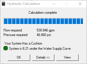
Pressing the Details button will expand the dialog box and display the number of passes required to balance the system.
When you press the View button, the Calculation Summary will appear. You can now prepare and print reports as you did for Tutorial #1.