Appearance
Tutorial #5a: Grid Project
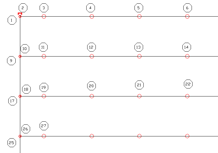
Open HydraCALC V50 and start a new file. Go to View > HydraCALC Sizer. Set up a grid as shown here.
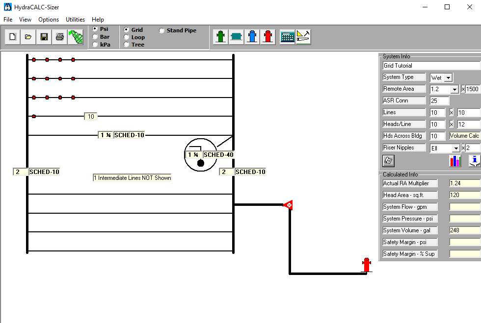
The system is Wet with a 1.2 shaped remote area covering 1500 square feet. The feed main connection is 25 feet above the last grid line. There are 10 grid lines, 10 feet apart. There are 10 heads per line, 12 feet apart. The riser nipples have an elbow at the top and are 2 feet long. Both mains are 2" Schedule 10. The riser nipples are 1 1/4 Schedule 40. The grid lines are 1 1/4 Schedule 10.
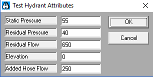
Press the City Supply Test Point button to add a city supply to the Graphic. Enter the water supply as shown.
The underground pipe and mains will be as shown here.
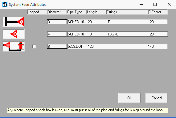
The feed main will be 20 feet of 3" Schedule 10 with an E for an elbow. The system riser will be 18 feet of 4" Schedule 10 with a G (gate), Avk (Viking alarm) and an E (elbow). The underground will be 120 feet of 6" Class 52, Cement Lined Ductile Iron 52CEL-DI with a T (tee). The C-Factor for the underground will be 140 and all others will be 120. Press OK to exit.
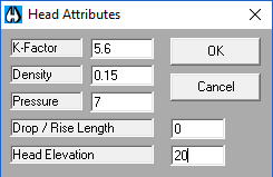
Pick one of the red colored heads to open the Head Attributes dialog box. Fill in the values as shown here.
Press the Calculate Results button and you should get the data shown here.
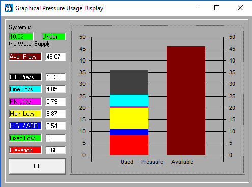
You should have about a 10 PSI cushion. Press OK to exit back to Sizer.
Press the Build Hydraulic Input & Exit button to export the data to HydraCALC. The Save As dialog box will appear.
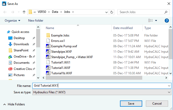
Enter Grid Tutorial .WX1 and press Save. You will exit Sizer and HydraCALC V50 will reappear. Review the data to ensure it is as you intended.
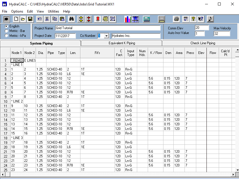
Line 1 is the most remote grid line. Note the Ls and the Rs in the length column. The L6 indicates that Node #2 is 6 feet to the left of Node #3. Node #2 is at the top of the riser nipple on the secondary main. The R78 indicates that Node #7 is 78 feet to the right of Node #6. Node #7 is at the top of the riser nipple on the primary main.
The image below shows the hydraulic reference points for the remote area.
Select Water Sources from the View pull-down menu to confirm the City Supply data and then exit. You should have 55 PSI static and 40 PSI Residual @ 650 GPM. The elevation should be 0 and add a 250 GPM Hose Allowance.