Appearance
Using Pressure Reducing Valves
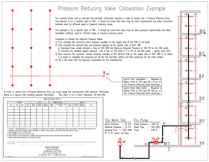
The following is a description and example of how to obtain the necessary information to utilize pressure reducing valves in your systems. The PRV manufacturer will require static and residual supply side pressures as well as system side demand in order to calibrate the valves.
Supply Side Static Pressure
First, calculate the maximum static pressure available on the supply side of the PRV at all levels.
Calculate the maximum static pressure at the pump by adding the city static pressure to the fire pump maximum churn pressure. The city Test node and the fire pump are at the same elevation therefore, an elevation correction is not required.
Maximum Static = 90 PSI + (150 psi x 1.18) = 90 + 177 = 267 PSI at the pump elevation.
The maximum static pressure at each PRV equals the maximum static pressure at the pump reduced by the elevation above the pump.
The fire sprinkler outlet on the 10th floor (FS10) is 115 feet above the fire pump.
Maximum Static FS10 = 267 PSI - (115 Ft x .4331 PSI/Ft) = 217.19 PSI
The hose outlet on the 10th floor (H10) is 110 feet above the fire pump.
Maximum Static H10 = 267 PSI - (110 Ft x .4331 PSI/Ft) = 219.36 PSI
Subtract the elevation pressures to determine the Maximum Static Pressure at each outlet following the previous examples.
See the chart below.
System Side Demand
Calculate the demand flow and pressure required on the system side of each PRV. The standpipe top hose outlet demands a flow of 250 GPM at 100 PSI minimum at the PRV outlet plus 250 GPM at the next lower outlet. For the sprinkler system demand, use a flow of 225 GPM at 110 PSI plus a 100 GPM inside hose allowance at each PRV outlet. We will assume that this is typical for each level.
Supply Side Residual Pressure
Calculate the maximum residual pressure available at the demand flow on the supply side of each PRV at all levels. It will be easier to calculate the pressures for all sprinkler system outlets first, then the hose outlets. For this calculation all safety margins are taken on the system side of the PRV and the remainder of the standpipe and supply pipe will flow at the maximum pressure that the combined city and fire pump can provide.
Calculate from the top sprinkler system or hose outlets using the demand flow for each to the city supply leaving NO Safety Margin. (To find the maximum start residual pressure add the safety margin pressure to your start pressure.)
This is the Initial Input Screen used to calculate the maximum residual pressure available at the demand flow on the supply side of each PRV at all levels. Start with the Demand Flow (225 GPM) and Pressure (110 PSI + 10 PSI Safety). (Any start pressure will do to begin with as we will be adding the safety margin back in and recalculating.)
The initial calculation is 83.8 PSI below curve. Add this to the start pressure (120 + 83.8) and recalculate.
Adjust the start pressure until the safety margin is equal to or very close to 0.0 PSI. This will provide the node pressures with the given water supply and pump.
In this example, 203.78 PSI was used.
Note: A separate calculation is required to find the maximum pressure for the first floor Node FS1 as this is not an outlet along the hydraulic path we are currently calculating.
Here is the Calculation Summary. The maximum residual pressures available for the fire sprinkler systems at the 10th and 2nd floor PRV s are shown below.
The maximum residual pressure available at the fire sprinkler system PRV for all the other floors can be quickly found by subtracting the friction loss of the 2 1/2" pipe from the pressure available at each Fire Sprinkler system node along the standpipe.
Examples - (At node FS10, 206.00 - 2.216 = 203.78 PSI) (At node FS2 247.905 - 2.216 = 245.69 PSI)
All the maximum residual pressures can now be supplied to the PRV manufacturer.
Note: The actual required pressure on the system side of the PRV must include the safety margin desired. Therefore, the minimum pressure required is 120 PSI = 110 PSI as calculated + (10 PSI Safety).
The fire sprinkler system demand flow is 225 GPM with a required pressure of 120 PSI.
Repeat the calculation to determine the maximum residual pressure available at the Hose PRV for all the floors.
The Initial Input Screen is used to calculate the maximum residual pressure available at the hose flow on the supply side of each PRV at all levels. The standpipe top hose outlet demands a flow of 250 GPM and Minimum Pressure of 100 PSI at the PRV outlet plus 250 GPM at the next lower outlet. Any start pressure will do to start since we will be adding the safety margin back in and recalculating until there is no safety margin remaining. 181.39 was the final pressure used in this example to get a zero-safety margin.
The maximum residual pressure available at the Standpipe demands at the 10th and 2nd Floor Hose PRVs are shown below.
The maximum residual pressure available at the Hose PRV for all the other floors can be quickly found by subtracting the friction loss of the 2 1/2" pipe from the pressure available at each Standpipe Hose node along the standpipe.
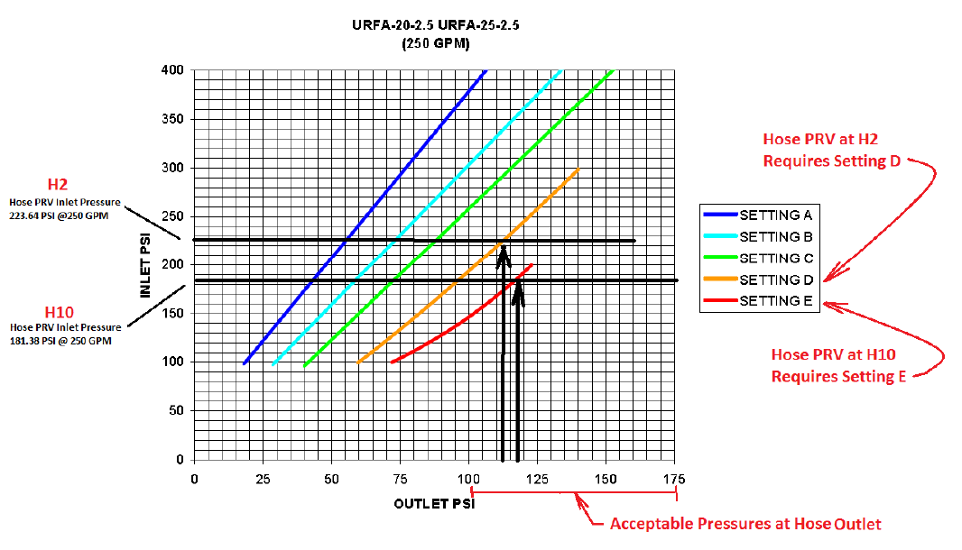
Examples - (At node H10, 184.07 - 2.693 = 181.38 PSI) (At node H2 226.33 - 2.693 = 223.64 PSI)
All the maximum residual pressures can now be supplied to the PRV manufacturer.
Below is an example of a field adjustable PRV made by Elkhart Brass Fire Fighting Equipment.
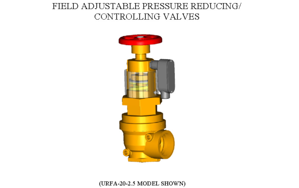
Follow the manufacturer s guide for proper field adjustment of the pressure reducing valves. Similar hydraulic pressure information is required to factory set or to field adjust a PRV.