Appearance
HydraCALC Sizer - Graphic Area
When you have completed the System Info area and selected a System Type with the radio buttons, a system will appear in the Graphics area.
The system shown above is loaded automatically each time you start the program. You can use it as a diagnostic test to make sure that your software is functioning correctly. For this example, Grid was selected.
The red dots are active sprinklers and the black lines are pipes. Try pressing the Grid, Loop and Tree radio buttons to see what the other systems look like. To help with clarity, the program will not show all the branch lines for larger systems. The number of lines not shown will be displayed. The red triangle is your system riser.
Specifying Pipe Sizes
You can change your pipe sizes and types by clicking on the screen.
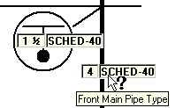
Here, the cursor is hovering over a grid Front Main.
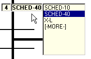
When you click on it, a drop-down list appears where you can select your pipe type.
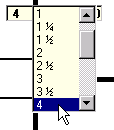
When you pick on the size, a drop-down list appears where you can change the diameter. Use the tool tips when hovering over a pipe to show you what category it is. These categories include riser nipples, mains, branch lines, etc.
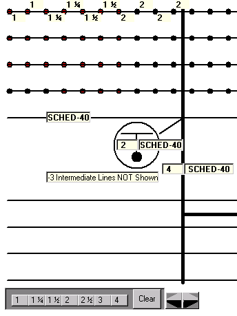
You can select individual branch pipe sizes for loops and trees. Pick on the size and a list will appear where you can make your selection. The pipe type box, shown here as SCHED-40, is used to set the pipe type for all branch lines.
You can also set the pipe sizes by using the Size Bar at the bottom of the screen. Use the Clear button to delete all branch line sizes. Begin pressing size buttons. The sizing will begin at the most remote line and continue until the main is reached.
Use the arrow buttons to position the main.
Setting Up Head Information
The number of operating heads and the shape of the remote area will be determined by the information you enter into the System Info box.
To enter the information for your heads, click your mouse on any of the operating (red) heads. The dialog box shown here will open. Enter the K-Factor, Density, Minimum Pressure and Elevation. If you have drops or sprigs enter the length in the provided field. If you do not have drops or sprigs, leave this field blank. The Drop/Rise Length and Head Elevation are in feet for the PSI setting and in meters for the metric settings.