Appearance
Utilities Menu - Alter Pipe/Fittings
Summary
Selecting Alter Pipe / Fittings from the Utilities menu opens the Pipe / Fitting Input dialog box. This is a central location for defining and managing the components used in your fire sprinkler system designs within HydraCALC. Users can define pipe types, fittings, and valves, as well as input pressure loss curves for items with non-linear losses. The database comes pre-loaded with common items, and users can add custom components as needed.
How Do I Use Alter Pipe / Fittings?
Starting the command will open the Pipe / Fitting Input dialog box.
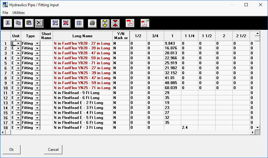
Use this box to define the pipe types, fittings and valves that you will use when building your systems. The database ships with common items. You can add additional pipe types, valves, fittings and pressure loss curves as you need them. In the Units column select E for English units, M for metric units or a Z for a chart loss. In the Type column select Fitting, Flex, Pipe or Curve.
In the Short Name column, you can enter an abbreviation for the item. For example, E is entered in the shipped database for a 90 Standard Elbow. The short name can be up to 3 characters, but the first character must be a capital letter followed by lower case letters. A short name must be present for the fitting to appear in the Fitting Input dialog box list.
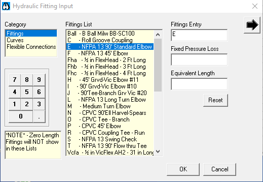
This E will appear when you add a 90 Standard Elbow in the Fitting Input dialog box. Also, the HydraCALC Sizer program will detect these elbows (or E s) in the graphic view of the system. See the Fitting Usage Definitions under Utilities in the HydraCALC Sizer section of this manual for more details.
When the calculation begins, the program will look in the database to find out what the equivalent length will be for the size of the 90 degree Standard Elbow.
The only short name that can be used with pipe types is S40 and must be used once to identify the English Standard Schedule 40 pipe type and once to identify the Metric Standard Schedule 40 pipe type. All fitting length adjustments are based on this pipe type. This has been preset and should not be changed.
The Long Name column is for entering a descriptive term for your pipes, fittings or valves. These fitting and valve descriptions will appear in the Fitting Input dialog box.
The Y/N Mark or C-Factor column is used to enter a Y or a N for valves and fittings or the C-Factor for pipes. The Y/N option is to allow adjustment of fitting equivalent lengths for non-Schedule 40 pipe as per NFPA 13. The default is Y for YES to allow. Enter N for NO adjustment.
The Nominal Size area is used to enter equivalent lengths for fittings and valves or the actual internal diameters for pipes. Equivalent lengths are entered in feet for English units and meters for metric units. Internal diameters are entered in inches for English units and millimeters for metric units.
Entering a Chart Loss
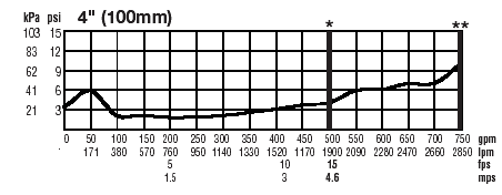
Some valves are best not expressed as an equivalent length because their losses are nonlinear with respect to flow. Chart losses can be supplied by the manufacturer showing pressure losses over a range of flow rates.
You can enter these chart losses in HydraCALC to form a graph.
For example, let s assume that you want to input the data for a 4" Ames 3000ss Double Check Detector assembly. The manufacturer's flow curve is shown below.
Move towards the bottom of the list and find the Ames 3000SS backflow valve.
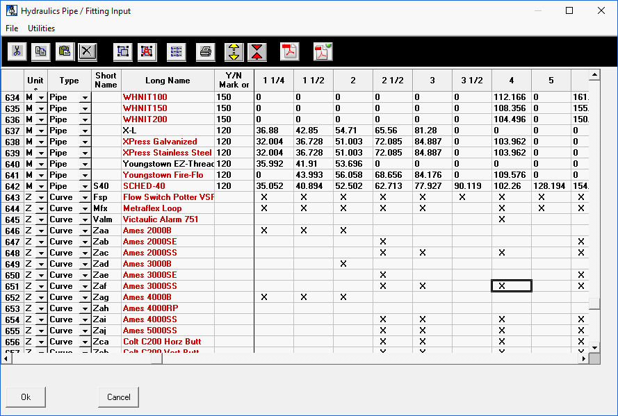
An X appears when the size has pressure loss data available. Pick the X for the 4" size. The pressure loss curve for the valve will appear.
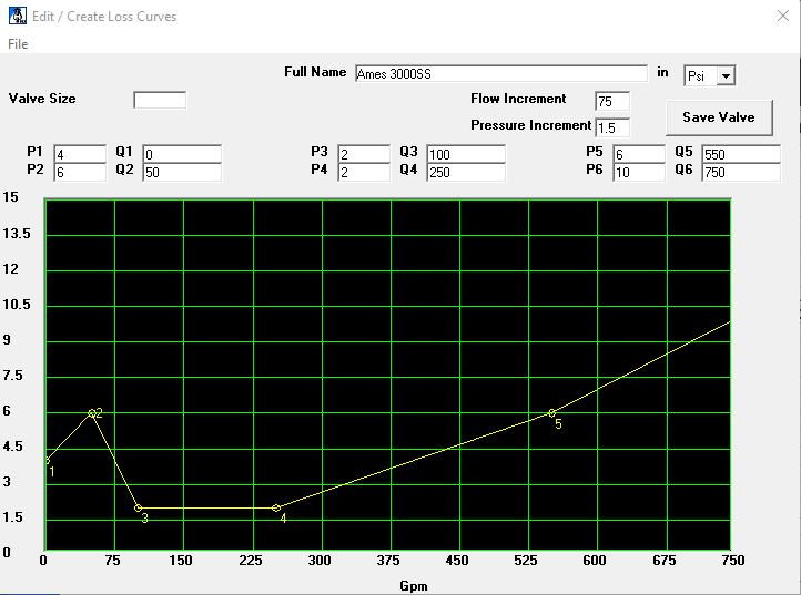
The data here should correspond to the manufacturer's data. When specifying your own valves, enter the data in this manner.
You can adjust the chart axes by entering values in the Flow Increment and Pressure Increment fields. You can also drag the numbered points with your mouse on the curve.
When your data entry is complete, press the Save Valve button to return to the dialog box. Now, when you use the short name in your system, the calculation program will determine the pressure loss based on the graph.
Pipe / Fitting Utilities
Use the Cut, Copy, Paste and Delete buttons at the top of the dialog box to modify rows.

The Load Single File and Load All Files buttons allow you to import updated pipe and fitting tables that are available from time to time on Hydratec's support and download site.
For more information on these commands, see the HydraCALC Database section of this manual.
The Duplicate button will copy the entry at the current cursor position and place it at the end of the list. Use the Print button to print the entire Pipe/ Fitting Table. Use the Insert Line and Delete Line buttons to insert and delete rows.
If a PDF file is associated with the part, highlight the part and press View PDF File to open the file.
Define PDF File will open the dialog box here. Use this dialog box to associate PDF files with parts. Copy the manufacturer s PDF files to a folder. The default folder is shown here.
Highlight the part on the left and the corresponding PDF file on the right. Press Add PDF to associate it.
Database changes require a restart of the program to take effect.