Appearance
Couplings

To jump to a video explaining the Couplings button, click here.
The Couplings button is used to insert multiple couplings along a run of pipe, as opposed to a single coupling using Revit's Split Element command. There are a few ways to add couplings using this tool, inserting couplings along only a single run of pipe, using continuous selection in order to select many runs of pipe, or placing couplings at the specific points a detail line passes over piping.
Summary
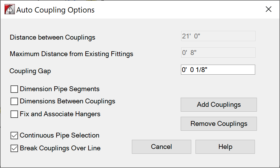
- Select the Couplings button from the HydraCAD ribbon.
- From inside the dialog box, you have multiple inputs that can specify the distance between couplings, Maximum Distance to Existing Fittings (This can also be interpreted as Minimum Distance to Existing Fittings) will tell the coupling not to be cut in if its too close to a POL, etc. Coupling Gap is a field where you can enter the gap of the coupling to avoid any issue with the fabricator regarding the pipe being longer than anticipated.
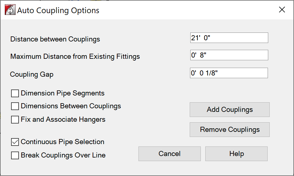
- Continuous Pipe Selection should be checked if you want to apply couplings to multiple runs of pipe, like all the branchlines for example. Leave unchecked for a single run.
- Break Couplings Over Line is used if you'd like to draw a detail line, splitting either one or multiple pipe at a desired position. You can click that line and it will put couplings where it intersects with any pipe beneath it.
- Checking any of the options to add dimensions will add them as couplings are cut in, according to whichever ones were selected. (Dimensions between couplings, Dimension pipe segments, etc.)
Example video of Couplings Button
How Do I Use The Button?
The Pipe Type / Routing Preferences / Union determines the family being used for the couplings. 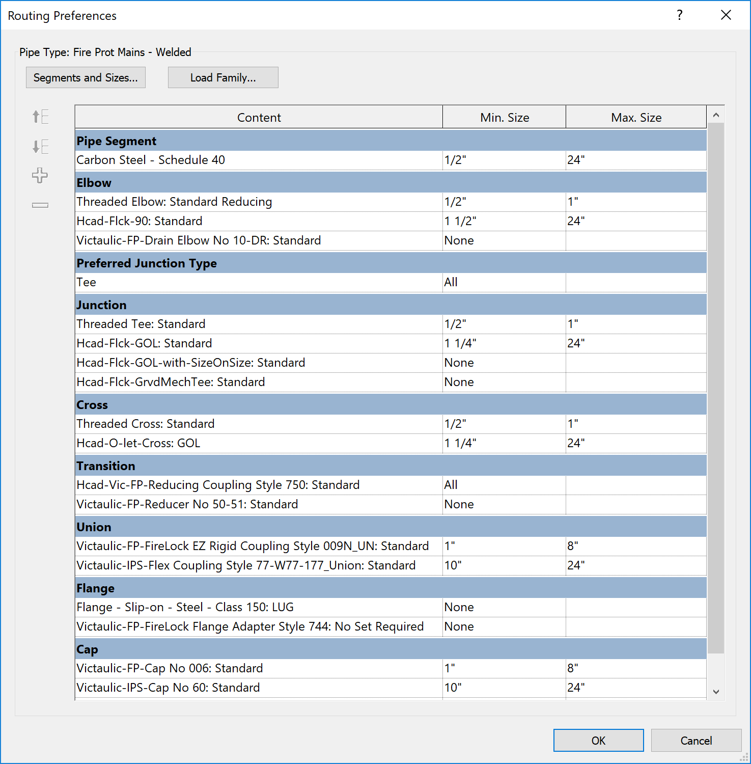
Imperial
Distance between couplings, input as decimal feet. Maximum distance from a fitting, input as decimal inches.  Metric
Distance between couplings, input as decimal meters. Maximum distance from a fitting, input as decimal millimeters. 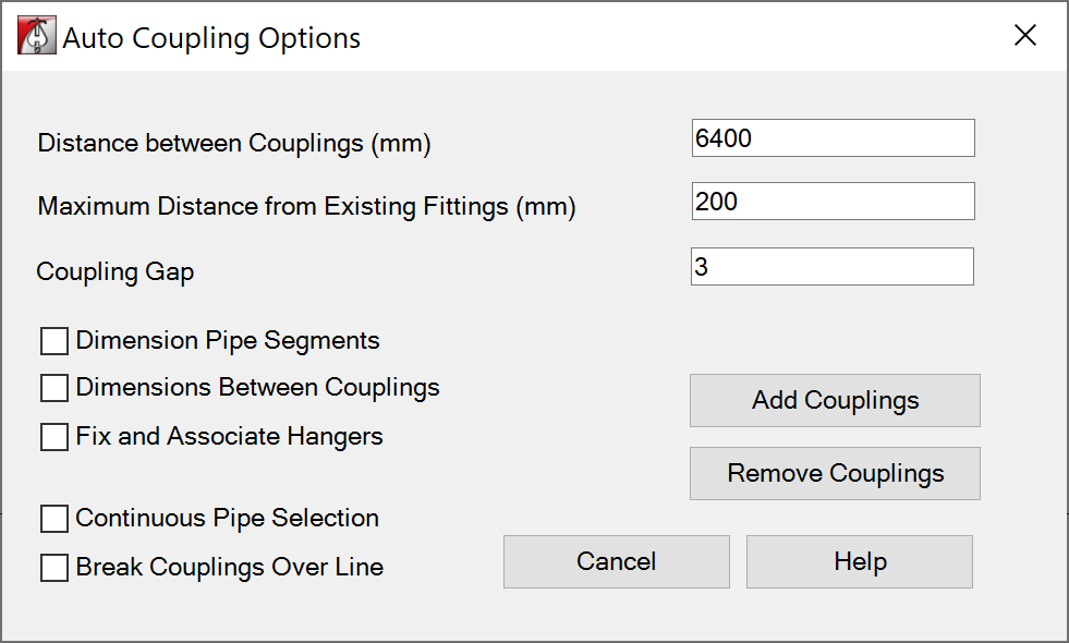
Add Couplings
 Continuous Pipe Selection:
If checked, you will be prompted to select another Detail Line. Right click mouse to Cancel, or Esc to quit.
Note: Coupling pipe run stops at an existing coupling, a change in direction (elbow), or a tee or cross with the same diameter outlets as the run’s pipe diameter.
Dimension Between Couplings
Note about couplings along sloped pipes and dimensions… Plan view dimensions may be shorter or longer, depending on the pipe slope. 
Dimension Pipe Segments

Fix and Associate Hangers
If checked, Ensure hangers and braces are attached to the newly created pipes.
This option may cause the tool to run much slower, regardless of the presence of hangers.

Break Couplings Over Line
Detail lines need to be added to view prior to running the command.
You will be prompted to select a detail Line.
Continuous Pipe Selection
If checked, you will be prompted to select another Detail Line. Right click mouse to Cancel, or Esc to quit. 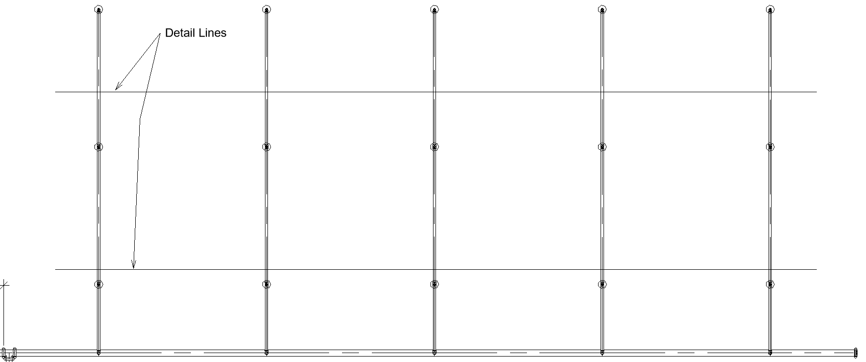 Couplings will be added at intersection of Pipe with Detail Line.
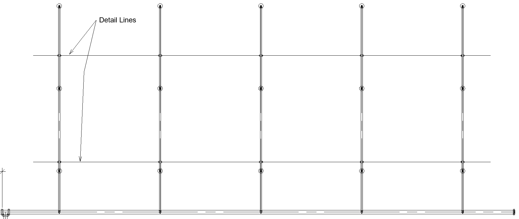
Remove Couplings
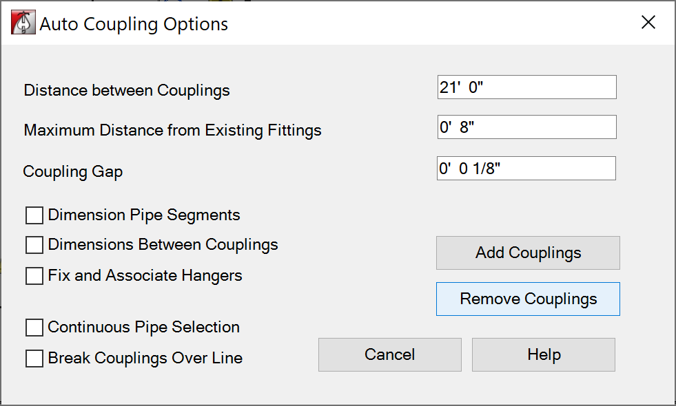 Will remove the couplings along the run of selected pipe.
Cancel
Cancels command and closes dialog box.
Help
Opens this help document.
Stocklisting Couplings
How to fix everything appearing as 'Generic Couplings' / or set which couplings appear in the stocklist:
- Also known as: How to 'Homogenize' couplings / coupling index values.
- Use the Coupling Index Decoder Ring PDF to find the Index value for your desired coupling
- A link to that resources can be found here
- Use the Loose Fitting and Coupling Schedule to get a list of all these 'generic' couplings
- Make a copy of the schedule, and remove the filtering
- Highlight all the couplings in the model, and change their override index value to the one you've chosen from the decoder ring.
If you'd like a more detailed explaination of this process, refer to the video linked below: How to Homogenzie Coupling Index Values
Additional Help (Videos and additional resources)
For more help regarding the Couplings button: click here
For other help that might be relevant to Couplings: click here
HydraCARDs (Troubleshooting)
For HydraCARDs regarding the couplings button: click here
For other relevant HydraCARDs: click here