Appearance
Spacing & Layout
To jump to a video explaining the Spacing & Layout button, click here.
Spacing and Layout is used to insert multiple sprinklers in a specified area, taking advantage of the background information to determine the distance between the sprinklers. This includes various configurations, modeling details, elevations and adjustments. Spacing and Layout provides an extensive dialogue box so the user can specify constraints, to generate a proposed sprinkler layout. This layout can subsequently be adjusted before actual modeling.
Sprinkler Configurations:
- Upright sprinklers – On sprigs or directly on the lines
- Pendant sprinklers – On 5 or more armover configurations
- Sidewall sprinklers – 6 or more sidewall configurations
Model detail options:
- Selection only of a new sprinkler
- Layout of sprinklers only
- Layout of sprinklers and branchline pipes
- Layout of sprinklers, branchline pipes and connecting armovers, drops and/or sprigs including flex drops
Elevation options:
- Level AFF (Above Finished Floor)
- At a specified slope AFF
- At a specified distance BTS (Below top of structure)
Adjustment Options:
- Entire row(s) of sprinklers at once
- Entire branchline
- Individual sprinklers along the branchline
- Individual sprinklers perpendicular to the branchline
Summary
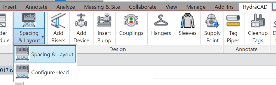
- Select the spacing & layout button
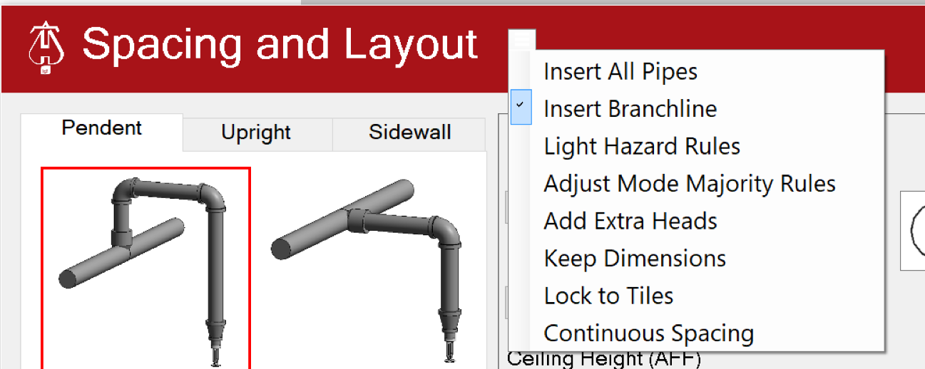
- From the three bar menu beside the Spacing and Layout title, select whether you'll be inserting only branchlines, inserting branchlines and connected piping to sprinkler heads, or only sprinkler heads.
- You can achieve all 3 of those results using this tool by checking Insert Branchline, Insert All Pipes or leaving all unchecked, respectively.
- Once you have chosen a desired option, select which configuration you want from the left-hand side of the dialog box. These are: Pendents, Uprights and Sidewalls
- Enter the sprinkler and pipe data in order to continue. Head data corresponds to the sprinklers used, Branchline data to the branchline pipe and connecting pipe data to the risers / armovers / drops that will connect to the sprinkler heads.
- Once all the sizes are entered and ready to be inserted, the Pick... button has a dropdown with a few options available
- Pick Light will allow you to select a light fixture that is centered within the tiles and matches the size of the tiles, the program will automatically determine the size of the room and place heads in the center of the tiles. NOTE: This must be used with an actual 3D modeled light fixture inside a Revit model.
- Pick Grid will allow you to select a point where two ceiling tile grids intersect, the program will automatically determine the size of the room and place heads in the center of the tiles. NOTE: This must be used with an actual ceiling grid inside of a 3D Revit model.
- Pick 3 Points will allow you to select in order (1) one corner of the room, (2) the diagonally opposite corner of the room, and (3) the intersection point of two ceiling tile grid lines. The program will treat the corners selected as the size of the room and automatically place heads in the center of the tiles. Pick 3 Points is typically the most used universal choice, meaning it can be used with Revit, Autocad and PDF Backgrounds.
- Or, with Upright or Sidewall head configurations selected, or with Pendent head configurations selected and Lock to Tiles turned off:...
- Pick Room allows you to select a room, the program will automatically determine the size of the room and evenly space heads and lines within it. NOTE: A room must be a modeled 3D object in a Revit background.
- (Most Common) Pick 2 Points allows you to select one corner of the room then the diagonally opposite corner of the room. The program will treat the corners selected as the size of the room and evenly space heads and lines within it. Pick 2 Points is typically the most used universal choice, meaning it can be used with Revit, Autocad and PDF Backgrounds.
- After choosing and completing the action as specified, sprinklers and pipe will be added to your project according to the data entered in Spacing and Layout
Example video of Spacing and Layout Button
How Do I Use The Button?
Main Dialog
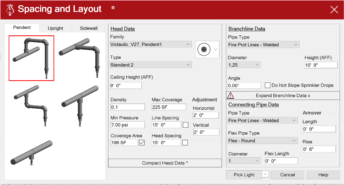
The Main Dialog has 6 sections.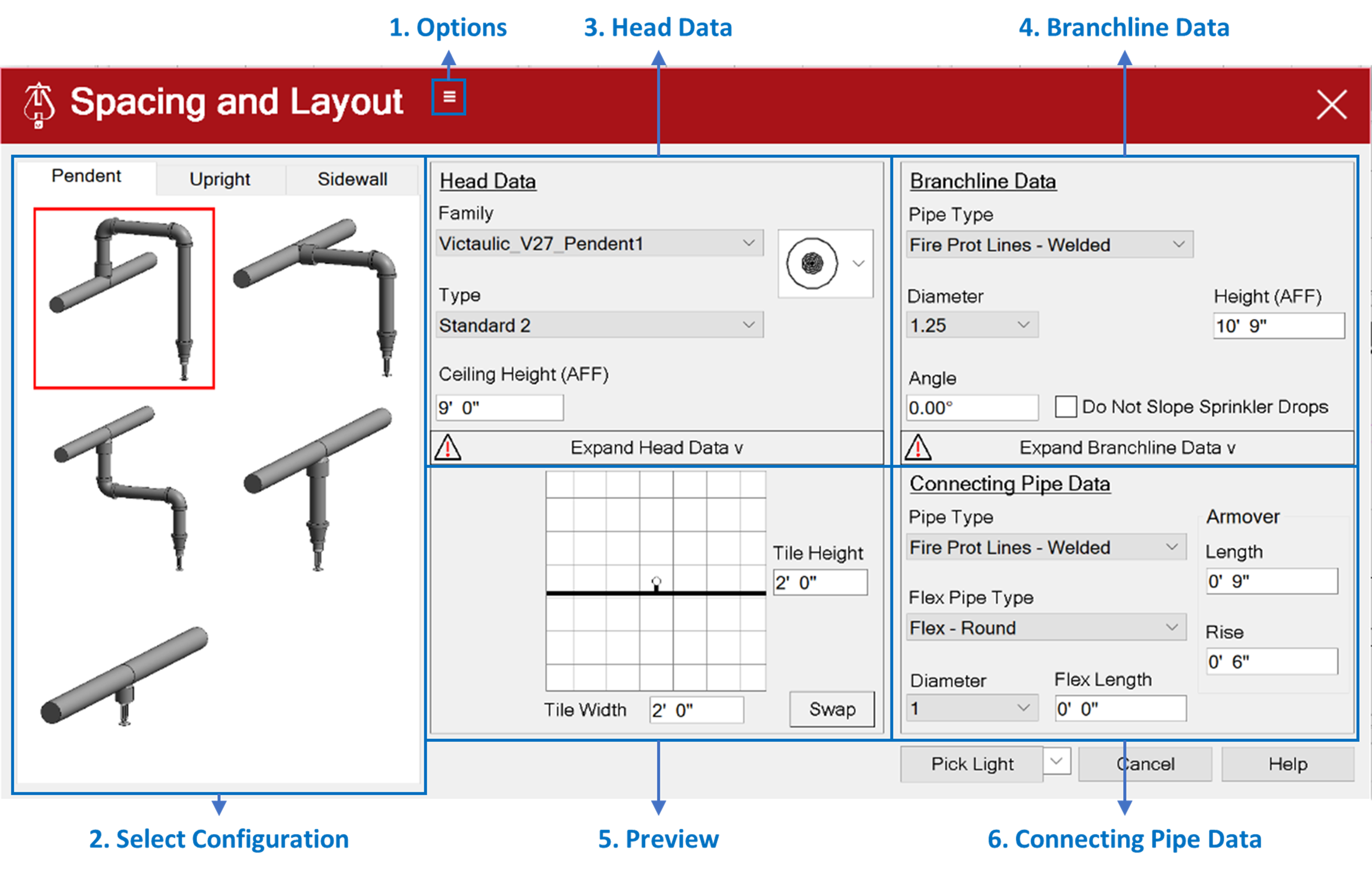
1. Options (Hamburger menu / Three bar menu)
Insert All Pipes:
- When checked, all branch piping and piping to sprinkler heads will be added to the model.
- Unchecked, only sprinkler heads will be added.
Insert Branchline:
- When checked, will model pipe without connecting sprinkler heads.
Light Hazard Rules:
- When checked, sprinklers may be located up to 9ft from any single wall within small rooms as defined by NFPA 13.
Adjust Mode Majority Rules:
- The entire branch line, or a single sprinkler will move when adjusted, depending on the number of sprinklers moved.
Keep Dimensions:
- Spacing dimensions will remain on the plan.
Lock to Tiles:
- When checked, pendent type sprinkler heads will be centered to ceiling tiles.
- Unchecked, will evenly space sprinklers to room boundaries. This allows spacing pendent sprinklers
- For smooth ceilings.
Continuous Spacing:
- When checked, the process of picking the room boundaries will repeat for the next room when piping and sprinklers are placed in the model. The setup dialog will not appear.
Press the Esc key to cancel the command.
- When checked, the process of picking the room boundaries will repeat for the next room when piping and sprinklers are placed in the model. The setup dialog will not appear.
2. Select Configuration
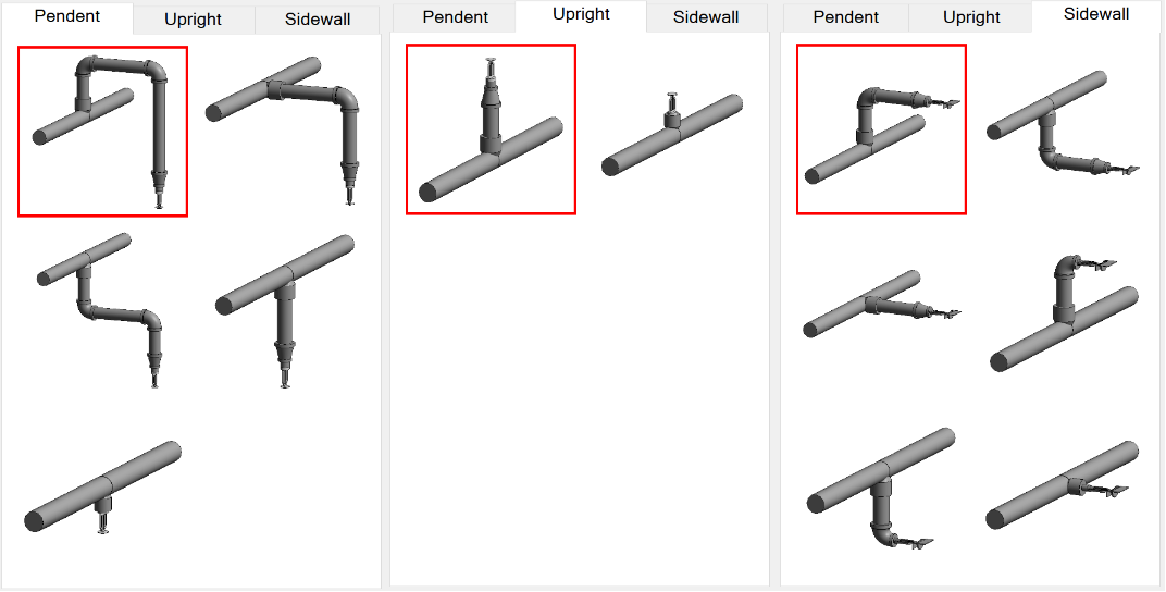
Start by selecting the type of head being used at the top, Pendent, Upright, or Sidewall
Then select the style of configuration desired by clicking on the picture that best matches
- Changing the selection will update the required information in the Connecting Pipe Data section
- Although all pictures show hard piping, all applicable configurations can be made with all or portions of it with flex pipe (as specified in the Connecting Pipe Data section)
3. Head Data
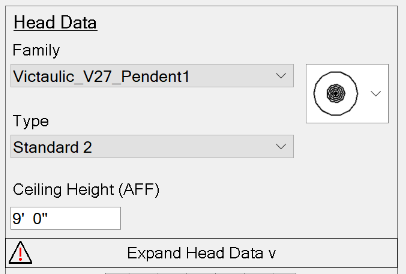
Family: pulldown list of all sprinkler families loaded into your model, as well as “New Head from Selector”, which allows you to select and load a new head into your project by choosing from Hydratec’s full database of sprinkler heads.
- Additional help on the Head Selector can be found here.
Type: pulldown list of all available types for the selected sprinkler family
Groups
- Groups can now be used in place of heads in Spacing and Layout.
- Under Family, near the bottom of the selection box, an option called Sprinkler Configuration Groups can be selected.
- This will also change Type into a selection box for the Sprinkler Configuration Group.
Groups will be located here for you to select. To find more detailed information on Groups, refer to the PDF here.
- Note: Groups will only show up in this list if they have “hcad” in the name, contain at least one sprinkler head, and contain exactly one open connector.
Once a group is selected, Spacing and Layout can be run as normal. A group will be placed where each head would have been, aligned so the head of the group is exactly where the normal head would have been.
If multiple heads are in the group, the tool will choose one that matches the current configuration (pendent, upright, or sidewall). When spacing is finalized, the groups will be ungrouped into each of the elements that made them up.
Ceiling Height (AFF):
- For Pendent heads, this will be the height that the sprinkler will be inserted
- For Upright and Sidewall heads, this is a read only field that shows the “Sprinkler Height (AFF)”, which is a calculation based on Branchline height, and how much of a rise/drop is specified in the Connecting Pipe Data section
Expand Head Data: - Click this box to show additional Head information - The exclamation point warning symbol will be shown until this button is clicked simply as a reminder that there is more information. If you have previously filled out this data, and no there is no need for additional changes, you can disregard the exclamation point warning symbol
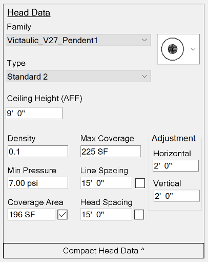
Density and Minimum Pressure: These are values that will be applied to all sprinkler heads added to the model during the current spacing and layout operation
Coverage Area:
- When corresponding checkbox is checked: the sprinkler coverage area for all sprinkler heads added to the model during the current spacing an layout operation will be the value input by the user
- When the corresponding checkbox is unchecked: the sprinkler coverage area will be set to be equal to the actual area as calculated by the spacing and layout tool
Maximum Coverage: Maximum sprinkler coverage area not to be exceeded during placement
Line Spacing:
- Maximum distance between branchlines
- With corresponding check box checked AND “Lock to Tiles” selected in the Options menu, the distance between branclines will be locked
Head Spacing:
- Maximum distance between sprinkler heads
- With corresponding check box checked AND “Lock to Tiles” selected in the Options menu, the distance between sprinkler heads will be locked
Adjustment (Horizontal and Vertical): The distance sprinklers and branchlines will be adjusted horizontally and vertically
Compact Head Data:
- Click this box to return the original view and redisplay the Preview
4. Branchline Data
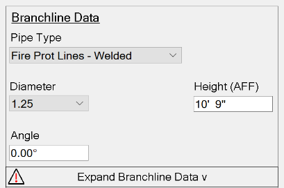
Pipe Type: Pulldown list of all pipe types in the project, will be used as the pipe type for the branchline piping
Diameter: Sets the pipe diameter of the branchline
Angle:
- Set to match the angle of the building to properly align sprinkler spacing and branch piping.
- An angle of 0 will allow piping to be oriented to 0 degrees and 90 degrees. If the building id oriented to 30 degrees, setting the angle to 30 degrees will orient the pipe to 30 degrees and 120 degrees
Height (AFF):
- The height that the branchline will be inserted at
- If the branchline is sloped this is the height of the low end of the branchline
Expand Branchline Data:
- Click this box to show additional Head information
- The exclamation point warning symbol will be shown until this button is clicked simply as a reminder that there is more information. If you have previously filled out this data, and no there is no need for additional changes, you can disregard the exclamation point warning symbol
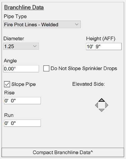
Slope Pipe check box:
- Check to slope branch piping
Rise:
- Set the change in Y, going up or down.
Run:
- Set the change in Y, going up or down.
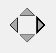
Elevated Side:
- Select wedge to indicate hide side of slope from low to high:
Do Not Slope Sprinkler Drops:
- Check to keep drops from sloping with branch line piping.
Compact Brancline Data:
- Click this box to return the original view and redisplay the Connecting Pipe Data
5. Preview
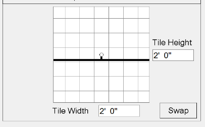
Preview Picture: Click the picture to rotate the orientation of the branchline with respect to the head (Example: from head to the north of the branchline, to the head west of the branchline)
Tile Height/Width: Dimension of the ceiling tiles, these values are only needed if “Lock to Tiles” is checked in Options sections
Swap: Changes the ceiling tile orientation, swaps the tile width and height
6. Connecting Pipe Data
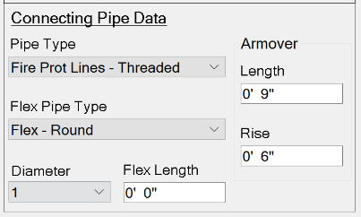
Pipe Type: Pulldown list of all pipe types in the project, will be used as the pipe type for the piping that connects the branchline to the sprinkler
Flex Pipe Type: Pulldown list of all flex pipe types in the project, will be used as the flex pipe type for the flex piping that connects the branchline to the sprinkler for the length specified in Flex Length
Diameter: Sets the pipe diameter of the piping that connects the branchline to the sprinkler
Flex Length:
- Sets the length of the connecting pipe(s) that will be flex pipe
- The length is measured from the sprinkler head. If the Flex Length is set to a distance greater than or equal to the length of all of the connecting pipe, then the entire connection will be flex pipe
Armover:
- The values are dependent on the configuration you choose
- Specify, where applicable, the length of the armover, or the rise/drop distance from branchline height
7. Action Buttons
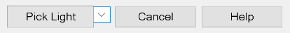
- The action button has several options that can be changed by clicking the pulldown arrow next to the button
- With Pendent head configurations selected and Lock to Tiles turned on:
- Pick Light: Select a light fixture, that is centered within the tiles and matches the size of the tiles, the program will automatically determine the size of the room and place heads in the center of the tiles.
- Note: This must be used with an actual 3D modeled light fixture inside a Revit model.
- Pick Grid: Select a point where two ceiling tile grids intersect, the program will automatically determine the size of the room and place heads in the center of the tiles
- Note: This must be used with an actual ceiling grid inside of a 3D Revit model.
- Pick 3 Points: Select in order (1) one corner of the room, (2) the diagonally opposite corner of the room, and (3) the intersection point of two ceiling tile grid lines. The program will treat the corners selected as the size of the room and automatically place heads in the center of the tiles. Pick 3 Points is typically the most used universal choice, meaning it can be used with Revit, Autocad and PDF Backgrounds.
- Pick Light: Select a light fixture, that is centered within the tiles and matches the size of the tiles, the program will automatically determine the size of the room and place heads in the center of the tiles.
- With Upright or Sidewall head configurations selected, or with Pendent head configurations selected and Lock to Tiles turned off:
- Pick Room: Select a room, the program will automatically determine the size of the room and evenly space heads and lines within it.
- Note: A room must be a modeled 3D object in a Revit background.
- Pick 2 Points: Select one corner of the room then the diagonally opposite corner of the room. The program will treat the corners selected as the size of the room and evenly space heads and lines within it. Pick 2 Points is typically the most used universal choice, meaning it can be used with Revit, Autocad and PDF Backgrounds.
- Pick Room: Select a room, the program will automatically determine the size of the room and evenly space heads and lines within it.
- With Pendent head configurations selected and Lock to Tiles turned on:
- Cancel: End the Spacing and Layout routine and returns to Revit
- Help: Displays this page on the default web browsing application
Adjusting and completing the proposed layout
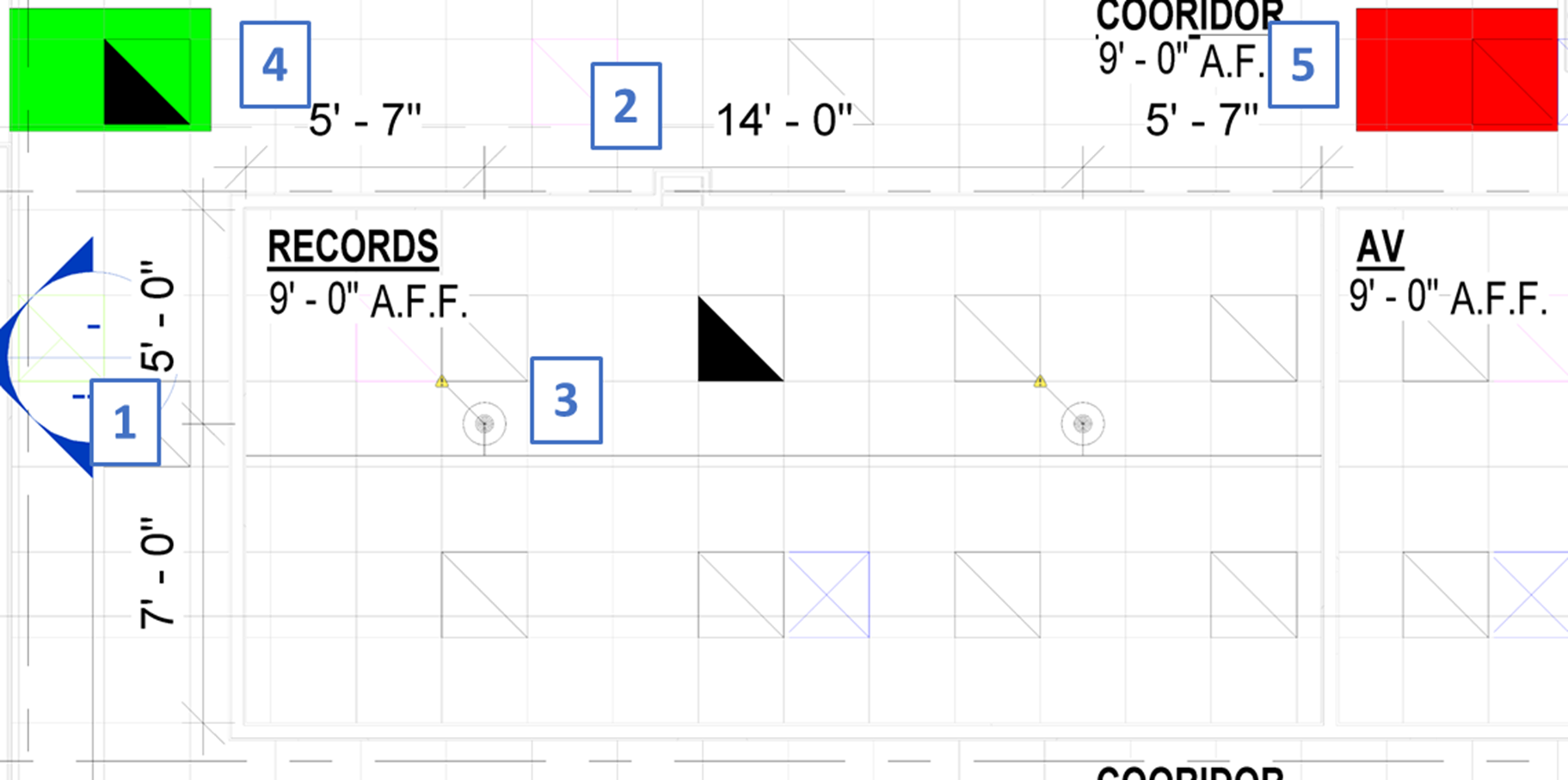
Adjusting Branchline Spacing:
- Clicking on either side of a dimension between branchlines (#1 in picture above), will move the branchline in that direction by the adjustment amount specified
- There is one extra branchline outside of the room in each direction that can be pulled into the room if necessary
Adjusting Rows of Heads:
- Clicking on either side of a dimension between rows of heads (#2 in picture above), will move the entire row of heads in that direction by the adjustment amount specified
- There is one extra row of heads outside of the room in each direction that can be pulled into the room if necessary
Adjusting Individual Heads:
- Clicking near an individual head (#3 in picture above) will move it in that direction by the adjustment amount specified
Inserting Heads (and Pipes):
- Clicking the Green Box (#4 in picture above), some users may see the word FINISH instead, will finalize the layout and insert the heads and pipes
- This can also be accomplished by hitting the ESC key on the keyboard and clicking the Insert Sprinklers button
Canceling/Revising the Setup:
- Clicking the Red Box (#5 in picture above), some users may see the word CANCEL instead, will bring the Spacing and Layout main dialog box back up to adjust any information, or cancel the routine
- If information is adjusted to return to spacing heads, click the Continue button in the Spacing and Layout main dialog box, the room will not need to be re-selected
- This can also be accomplished by hitting the ESC key on the keyboard and clicking the Revise Setup, or Cancel button
Additional Help (Videos and additional resources)
For more help regarding the spacing & layout button: click here
For other help that might be relevant to spacing & layout: click here
HydraCARDs (Troubleshooting)
For HydraCARDs regarding the spacing & layout button: click here
For other relevant HydraCARDs: click here