Appearance
Hydraulic Calculations
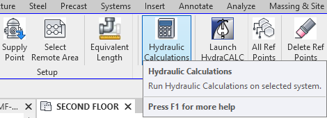
To jump to a video explaining the Hydraulic Calculations button, click here.
Hydraulic Calculations is used to, as the name implies, hydraulically calculate the fire protection system that is modeled in Revit. A prerequisite that must be met within the Revit model, prior to running Hydraulic Calculations, is that you need Operating Heads, a Connected Model, and a Water Supply.
Operating Heads and a Connected Model simply means that you need a fire protection model that's fully setup with sprinkler heads and pipe connecting everything together. To make the sprinkler heads count as Operating you need to set them as flowing, and assign them a remote area number which can be seen in the picture below.
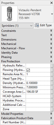
The Flowing checkbox must be filled with a solid (not grey) checkmark, and Remote Area Number must be assigned a numerical value. This must be true for all sprinkler heads in the project that are to be used in the Hydraulic Calculation.
Lastly, a Water Supply is needed within the project. This can be added into the project by using the Supply Point button, which can be found my clicking the link here.
Now that all of the prerequisites are met, and the model that needs to be hydraulically calculated is selected in the project either manually or via the System Walker, shown here, the Hydraulic Calculations button can be used and ran successfully, where some further information will be required.
Summary
- Prerequisite to running Hydraulic Calculations:
- You need Operating Heads, a Connected Model, and a Water Supply.
- Details about these are located above.
- To run Hydraulic Calculation:
- Click Hydraulic Calculations button
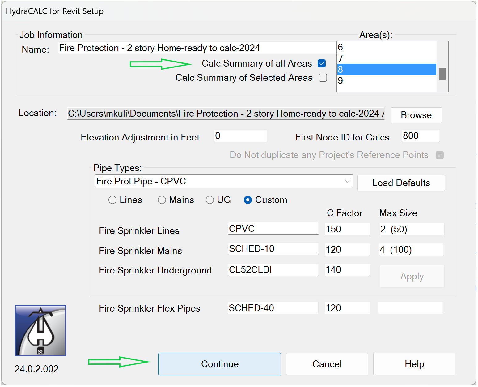
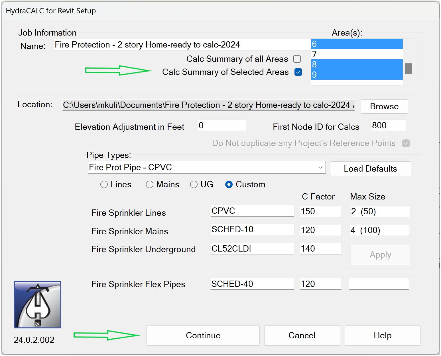
- The HydraCALC for Revit Setup dialog box will open.
- If the Continue button is greyed out or not selectable, Load Defaults for each Revit Pipe Type in the dropdown menu.
- More on this process can be read about here
- Once all the Pipe Types are defined and the Continue button is accessible, press it.
- Click Hydraulic Calculations button
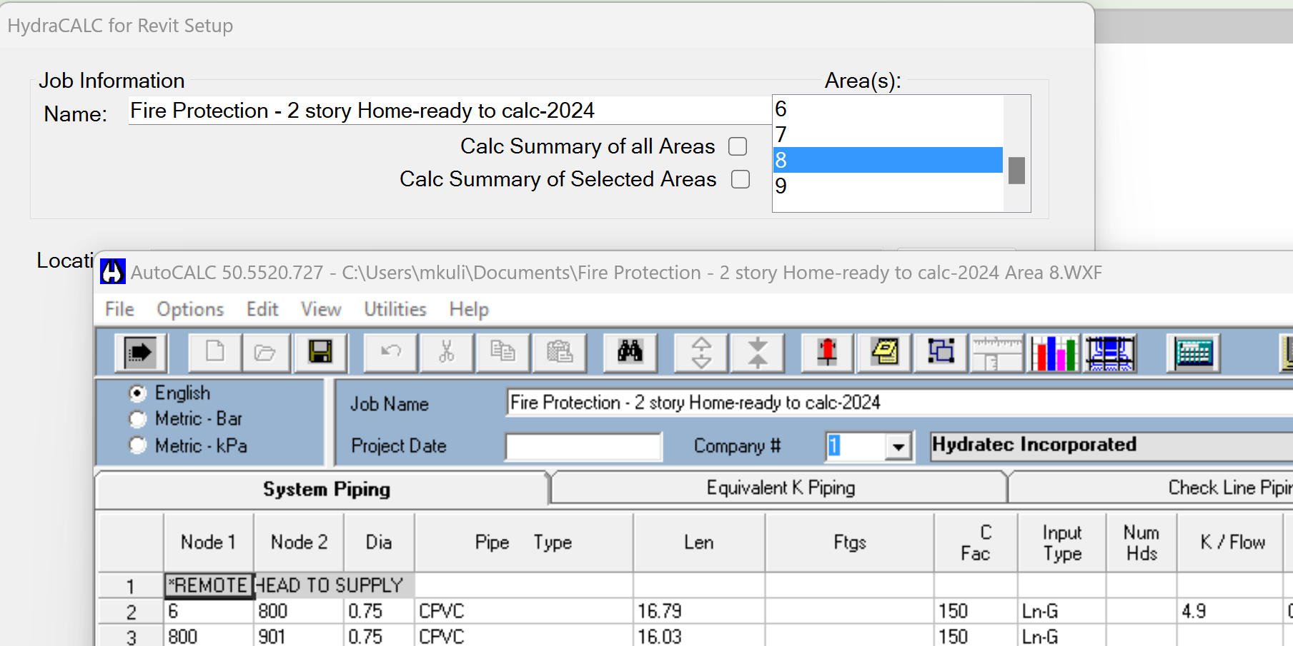
- HydraCALC's Hydraulic Data Input sheet will open with properties imported from the Revit model.
- Click
 Calculate
 - After the calculation is complete, exit the data sheet via the red X in the top right.
- After returning to the HydraCALC for Revit Setup dialog box, select Return to Revit
- When prompted to place down the Fire Protection System Demand Information Box, select an open area beside and out of the way of the current Revit model.
Example video of Hydraulic Calculations Button
How Do I Use The Button?
Click the Hydraulic Calculations button. This will bring up the HydraCALC for Revit Setup dialog box. Information may need to be entered here before being able to continue with the calculations. You will know this is the case if the Continue button within the dialog box is grayed-out and not selectable.
Warning.There has been an update to the Hydraulic Calculations program. If your dialog box does not look as it appears below, please click here to be brought to the older version.
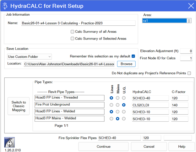
Job Information

Name: Defaults to the project’s name and can be changed as desired. Area: Dropdown list ao all areas that can be calculated for the selected system.
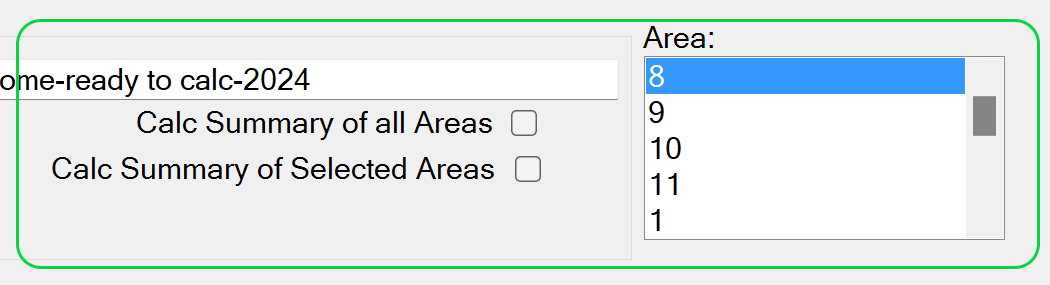
HydraCALC for Revit Setup screen Area(s) list box allows selection of one, multiple, or all areas for calc demand summary.
Moving the mouse cursor into the Area list will expand it.
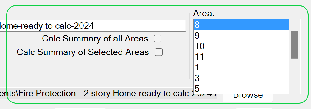
Note Pressing SHIFT and clicking the mouse or pressing SHIFT and one of the arrow keys (UP ARROW, DOWN ARROW, LEFT ARROW, and RIGHT ARROW) extends the selection from the previously selected item to the current item. Pressing CTRL and clicking the mouse selects or deselects an item in the list.
Calc Summary of All Areas
 Checking this box then picking Continue will QuickCalc all the Areas, regardless of selection.
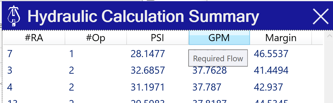
 Upon completion of all area QuickCalcs, the Hydraulic Calculation Summary dialog will open.
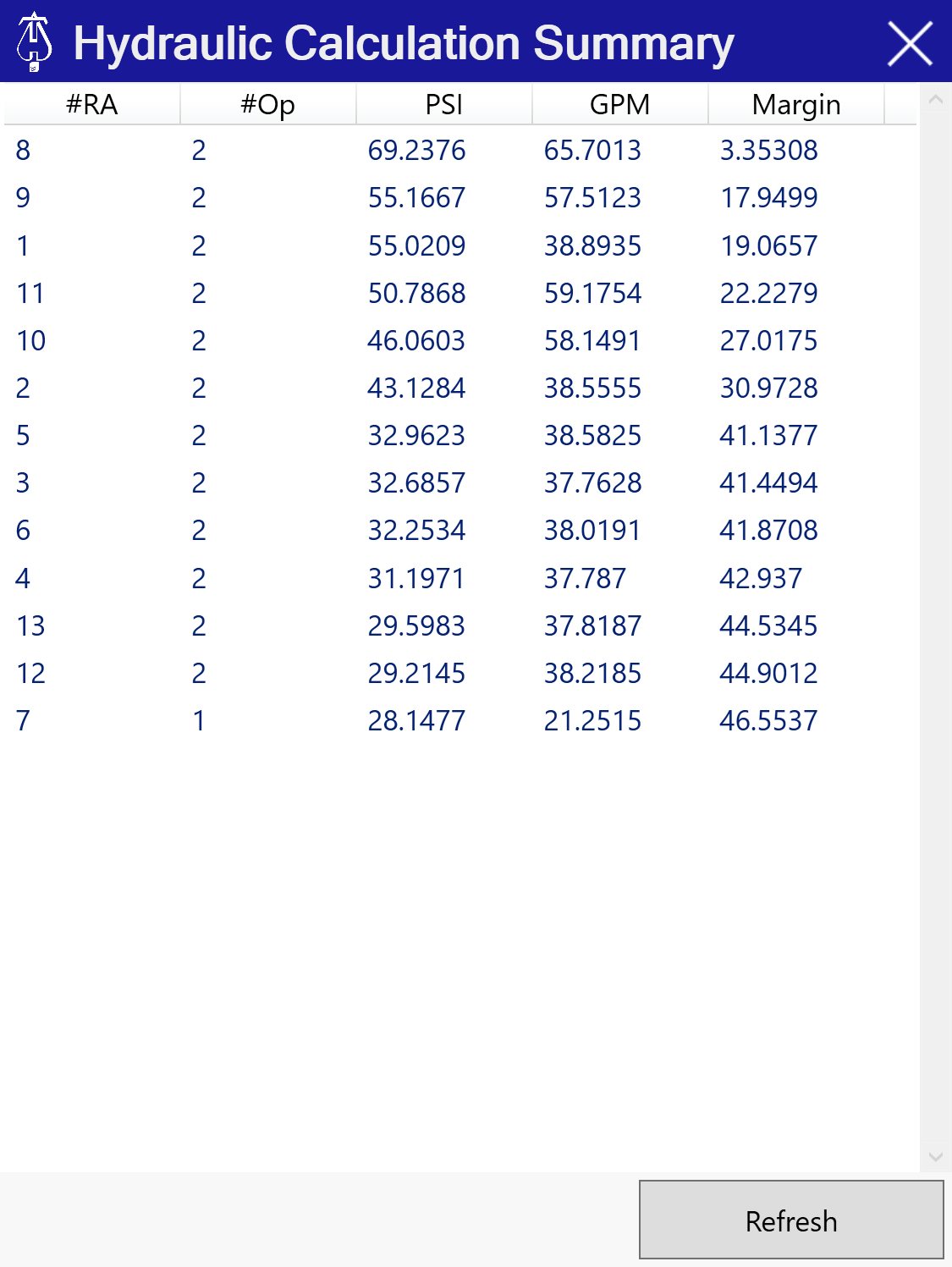
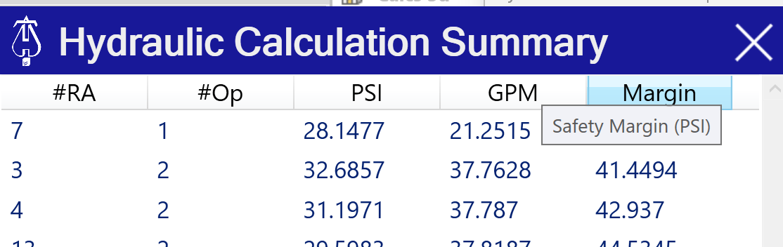
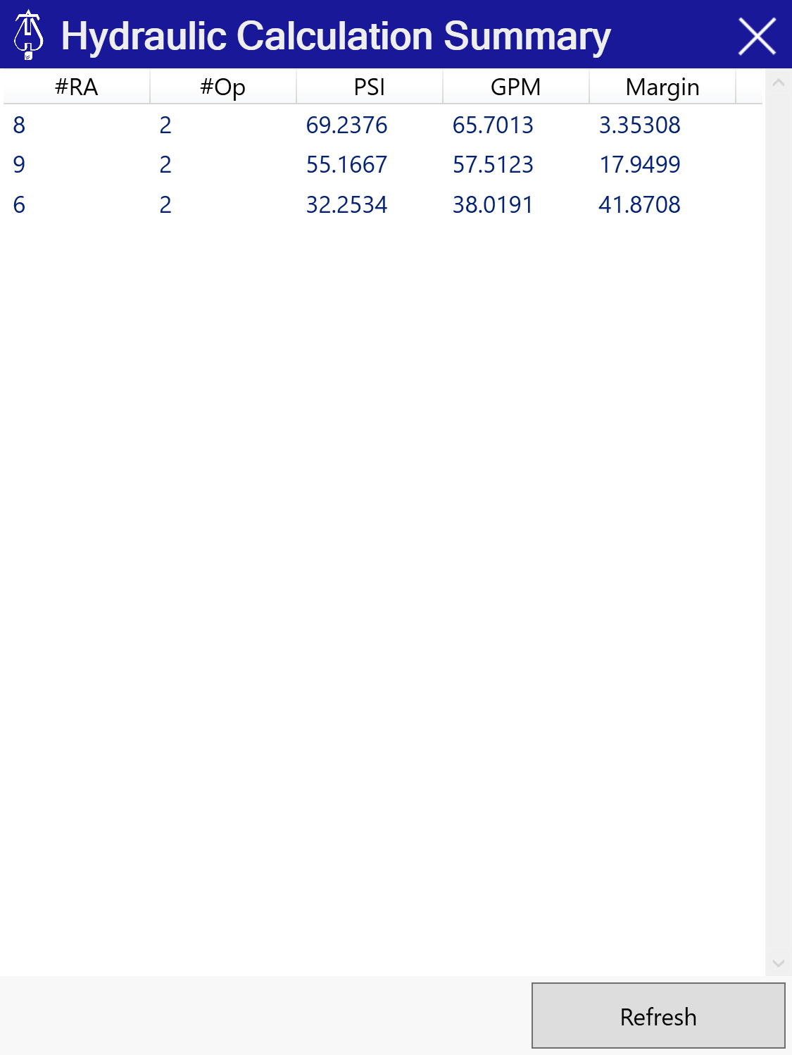
The areas are initially sorted by the area with the least safety margin at the top.
Clicking on the headings will change the sorting of the areas
Calc Summary of Selected Areas
 Checking this box then picking Continue will QuickCalc the selected Areas.
 Upon completion of QuickCalcs, the Hydraulic Calculation Summary dialog will open.
File Location Frame
The File Location frame allows you to specify where Hydraulic Calculation files will be saved. It includes two options:
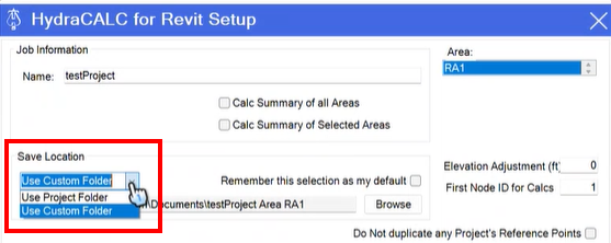
Use Project Folder
Select this option to save files in the project’s folder.
If the project is stored in the cloud or the path is invalid (e.g., does not start with a physical drive letter like C: or D:), the system defaults to the HydraCALC standalone location:
C:\HydraCALC\Version50\Data\Jobs[ProjectName]
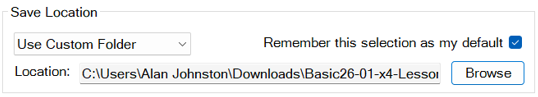
Use Custom Folder
Select this option to choose a specific folder for saving files.
Click Browse to navigate to your desired location. You can create a new folder if needed.
Check Remember this selection as my default to make this location the default for future calculations.
Remember this selection as my default
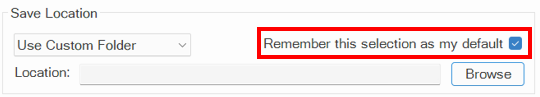
The Default button sets both the selected location type (Project or Custom) and the specific folder path as your default for future calculations.
If the chosen project folder is invalid, HydraCALC automatically substitutes the standalone default location.
The new default is set when you either press browse or continue while the checkbox is checked.
Elevation Adjustment
 In some cases a Revit project may have a datum elevation of 100 ft as 0(zero) elevation. The hydraulics file node points will reflect these elevations. Use this to globally adjust the node elevations in the HydraCALC file. A Negative number will lessen model elevations and a Positive number will increase the node elevations.
First Node ID for Calcs

Do Not duplicate any Project’s Reference Points

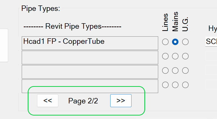
Pipe Type Mapping Grid
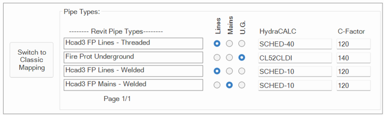
Review each Revit Pipe Type in the list
Ensure it is mapped to Lines, Mains, or Underground using the radio (circle) buttons.
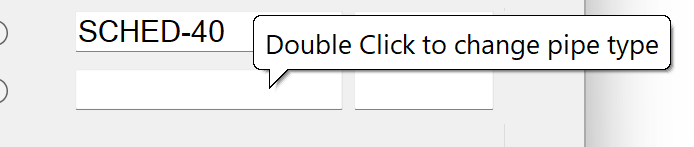
Newly added pipe types are automatically assigned a type, schedule, and C-factor, which can be adjusted by double clicking the respective fields.
Use the navigation arrows to move between pages if multiple pipe types (more than 4) exist. Blank entries are now very unlikely but will prevent you from continuing.
C Factor
If there are more than 4 Revit Pipe Types in the selected system use the page direction arrows to advance to the next or previous page.
Classic Mapping Option
Pick Switch to Classic Mapping to switch to classic mapping dialog. 
Load Defaults
If all the size mapping values are blank or some are missing, pick the Load Defaults button for values. 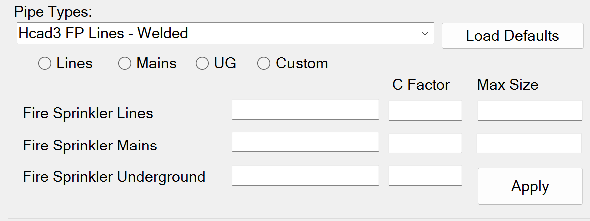
After clicking Load Defaults: 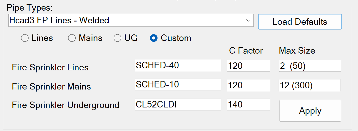
The size mapping properties for each Pipe Type can be entered manually to your specifications by picking the Custom radio button, or by clicking the Load Defaults button. Pick the Apply button when changes are made.
HydraCALC Pipe Type mapping: 
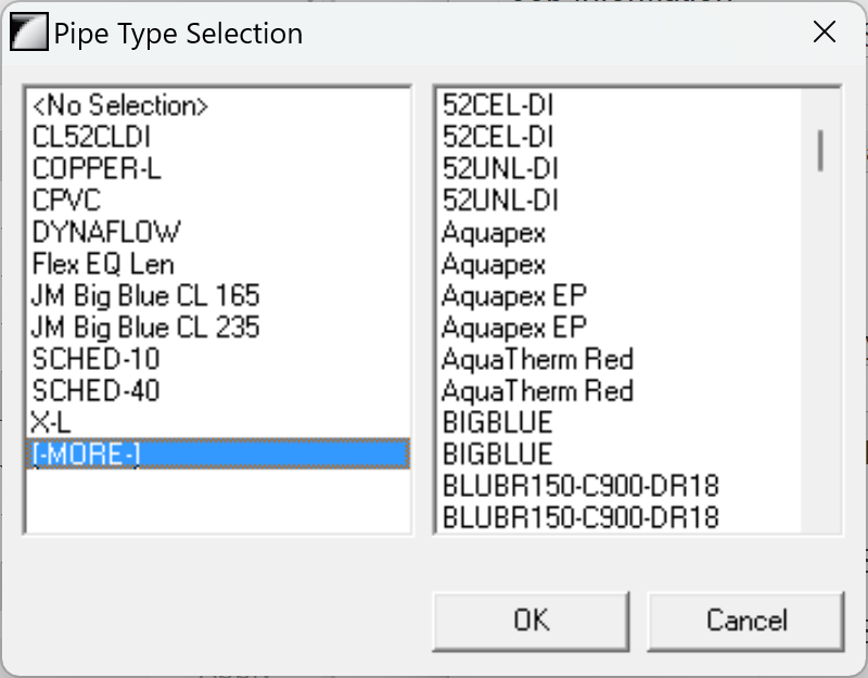
Double Click and select available types then OK to change.
C Factor mapping: Select value and change.
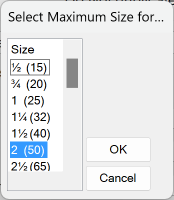
Max Size mapping:  Double Click and select available types then OK to change
You can also quickly group a Revit Pipe Type to a specific size mapping from the classic mapping screen, select the pipe type from the Pipe Types pulldown and pick the desired radio button
Here are some examples of those values:
Threaded Branch Line Pipe Types (ie: Hcad3 FP Lines – Threaded, Arms to …, etc): 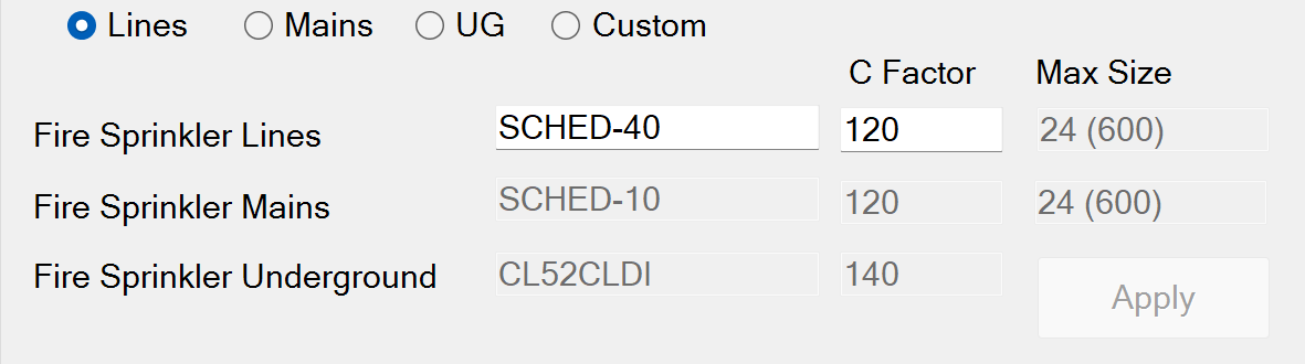
The setting shown above would ensure that those pipe types will be treated as lines in the hydraulic calculations and as shown would use Sched-40 and C=120. Enabled HydraCALC Pipe Type and C Factor values can be changed as needed.
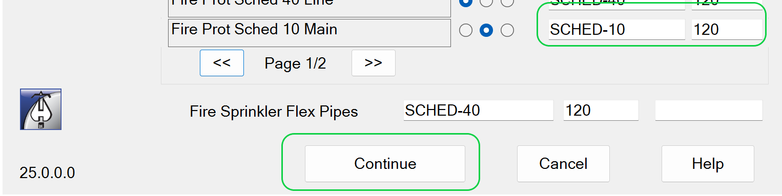
Welded Branch Line Pipe Types (ie: Hcad3 FP Lines – Welded, etc): 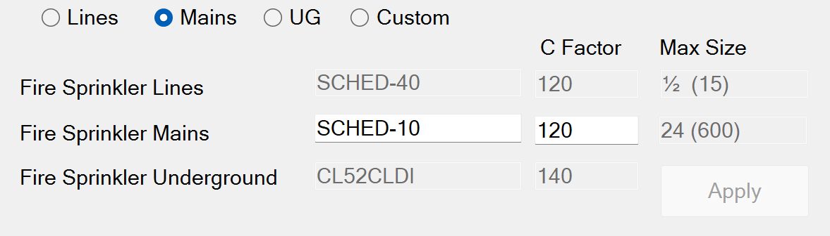
The setting shown above would ensure that those pipe types will be treated as lines in the hydraulic calculations and as shown would use Sched-10 and C=120. Enabled HydraCALC Pipe Type and C Factor values can be changed as needed.
Welded Main Pipe Types (ie: Hcad3 FP Mains – Welded, etc): 
The setting shown above would ensure that those pipe types will be treated as mains in the hydraulic calculations and as shown would use Sched-10 and C=120. Enabled HydraCALC Pipe Type and C Factor values can be changed as needed.
Underground Pipe Types (ie: Fire Prot Underground, etc): 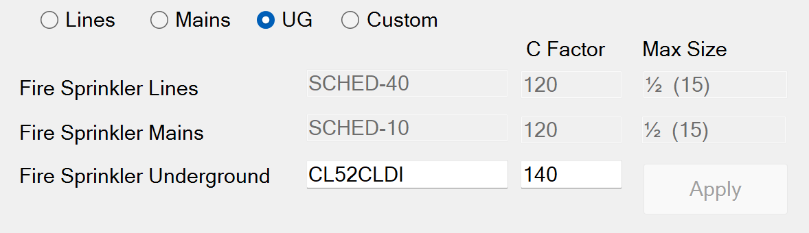
The setting shown above would ensure that those pipe types will be treated as UG in the hydraulic calculations and as shown would use CL52CLDI and C=140. Enabled HydraCALC Pipe Type and C Factor values can be changed as needed.
Once the information is mapped to the Revit Pipe Types once, it does not need to be done again on subsequent runnings of the Hydraulic Calculations process.
After each Pipe Type has the properties they need, and the changes have been applied, the Continue button should be selectable. On pressing it, a loading bar should appear on the top of the screen indicating the step of the process it is currently on and how far along it is.
Final Calculations
Upon review of the Hydraulic Calculation Summary, final calculations can be completed for the most demanding area.
You can only finalize calcs for one area at a time.
Un-check the Summary checkboxes.

If you select more than one area this dialog box will appear when picking Continue.
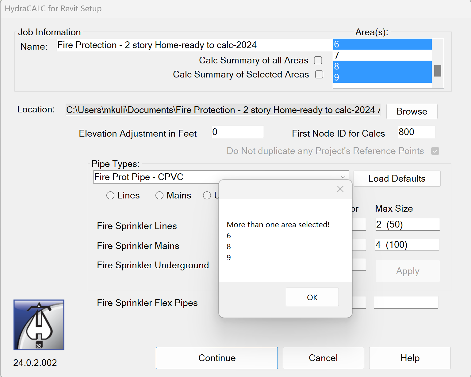
Pick one area from the Areas listbox to continue to final calculations.
How to Calculate Fluid Delivery Time
A fluid delivery time calculation is used to simulate the time it will take to get water from a valve to the remote sprinkler through air or nitrogen filled pipe, or through empty pipe. Like any hydraulic calculation, three (3) elements are required:
- 1: A designated flowing sprinkler with defined Kfactor, Area, Density, and minimum starting pressure.
- 2: A designated supply point on a fitting.
- 3: A connected model between the flowing sprinkler and supply point.
For more information on how to make a data file that can be used to calculate Fluid Delivery Time, click here
Additional Help (Videos and additional resources)
For more help regarding the Hydraulic Calculations button: click here
HydraCARDs (Troubleshooting)
For HydraCARDs regarding the Hydraulic Calculations button: click here
Listed below are options for further refining the HydraCARDs for Hydraulic Calculations. Please select the one that best matches where and when you encountered your error..
Please select the option corresponding to when, or closest to when, you encountered the error.
Immediately after clicking the Hydraulic Calculations button but before clikcing continue, click here
After clicking the Continue button, click here
During the loading steps before entering the spreadsheet, click here
In the HydraCALC Spreadsheet, click here
Upon Returning to Revit, click here
For other relevant HydraCARDs: click here