Appearance
Hangers
To jump to a video explaining the Hangers button, click here.
The hangers button is used to insert hangers / trapeze / seismic braces into the project either manually or automatically along a run of pipe.
Summary
- Select the Hangers button
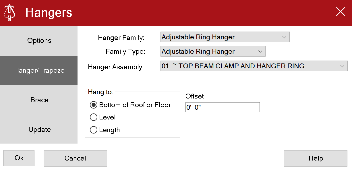
- Choose your desired Hanger Family and Hanger Type, then Hanger Assembly
- Hanger Family and Hanger Type affect the geometry / model that is inserted after you finish using the Hanger tool.
- Hanger Assembly corresponds to what will be sent / shown on the Stocklisting program. If your company has made adjustments to Stocklisting program to have your unique list of Hanger Assemblies, those will be shown here.
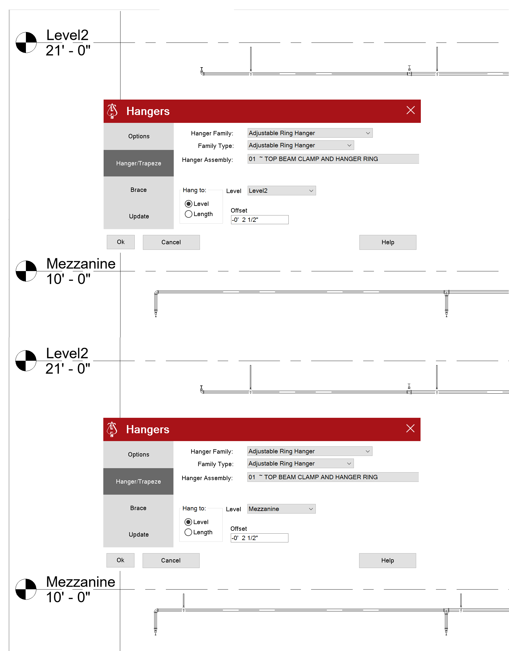
- Specify a length for the hanger, or choose a location for it to hang to under the Hang To: section.
- Hanging to a level will give an option to offset, should you need it.
- If you wish to making hangers along a run of pipe at certain intervals, select the Options menu on the left.
- From here, you can specify the minimum length pipe to hang and select Yes or No for auto-hanging along a run.
- The offset is the distance the first hanger will be placed, and the repeating offset is the length the next one will be placed along the run of pipe.
- When you are satisfied with your selections, click Ok and the hangers will be placed.
Example video of Hangers Button
How Do I Use The Button?
If no hanger families are not loaded in the model, the Version 9 hangers will automatically load.
If for some reason they do not, you will see this message.
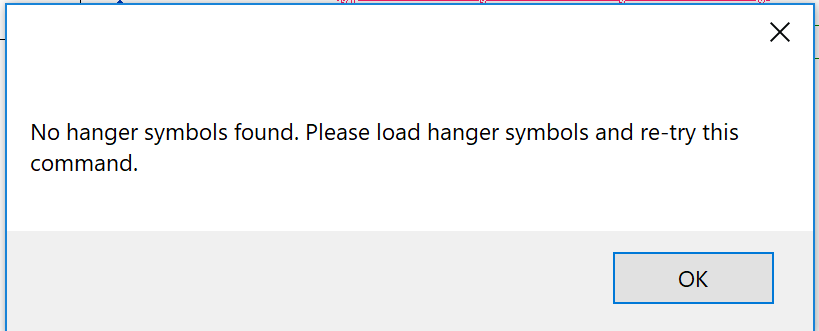
You may get the following error in a model with earlier versions of hanger families.
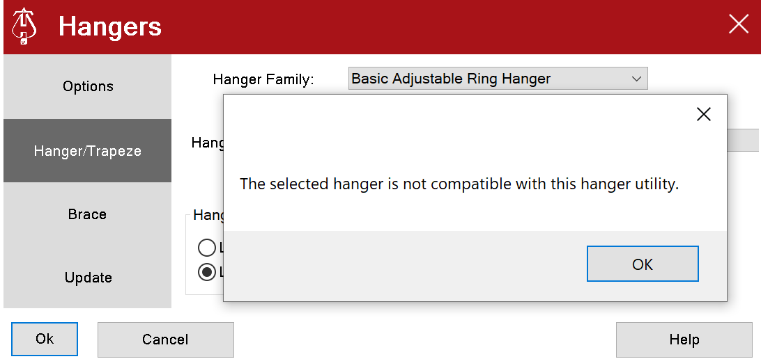
Run Setup and select one of the Version 10 hanger families
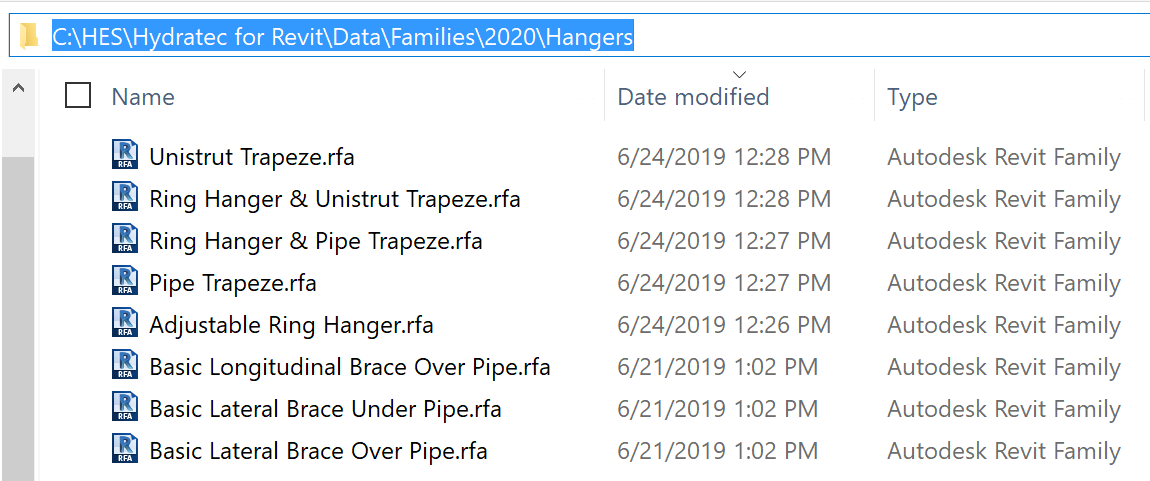
You may need to manually load the new Version 10 hanger families into an existing model containing Version 8 hanger families. Hangers can be found in the \HES\Hydratec for Revit\Data\Families\20xx\Hangers folder.
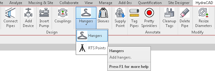
Pick the Hangers Button from the HydraCAD ribbon.
The main Hanger dialog box will display. 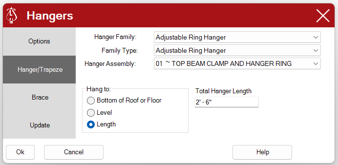
Hanger / Trapese
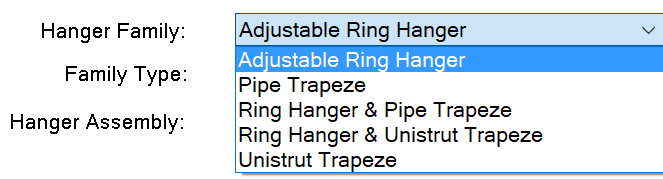
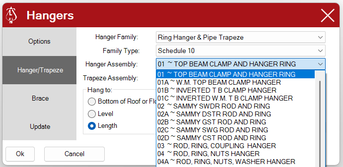
Hanger Family Pull down list of available (loaded) hanger families
Every family listed will have at least 1 type. The Hanger Family and Hanger Type affect the geometry / model that is inserted after you finish using the Hanger tool. 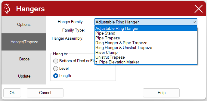
Family Type Pull down list of available family types
This a further refinement on the geometry that's going to be represented in your model. There can be multiple Hanger Types for each Hanger Family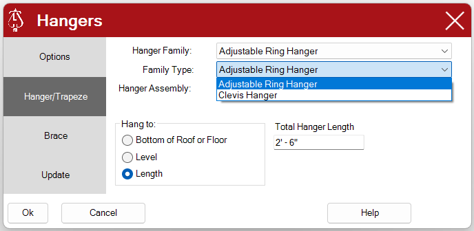
Hanger Assembly Pull down list of available HydraLIST hanger codes from HydraLIST hanger assembly database to associate with selected hanger.
Hanger Assembly corresponds to what will be sent / shown on the Stocklisting program. If your company has made adjustments to Stocklisting program to have your unique list of Hanger Assemblies, those will be shown here.
Hangers’ sizes are based on UL (Underwriter Laboratories) standards. Based on these standards, Adjustable Rings Hangers can be found up to 8”. Anything beyond that size will have to be found under other hanger types, such as CLAVIS.
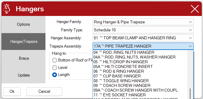
If a hanger family with a trapeze is selected, select a HydraLIST assembly for the trapeze.
When This same Hanger Assembly Drop Down List is available in the Brace Setup Dialog, your company may have set up Seismic Brace Assemblies in the HydraLIST program available on your computer.
The standard Hydratec Assemblies have traditionally not included Seismic assemblies. If you do not see the following assemblies in your drop down list and you want to make them available, click here for instructions and a video on how to add them to your HydraLIST Assemblies Data. That video is also accompanied by a PDF, which you can click here an access alongside the video.
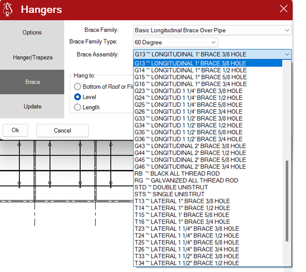
This is what the drop down would look like after adding these assemblies.
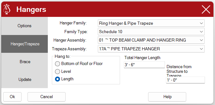
Hang to: Length
- Enter the total length of the hanger
Distance from Structure to Trapeze
- If a hanger with a trapeze is selected enter distance down from the referenced Level to trapeze pipe or iron.
Level
- Select the appropriate level for determining the hanger length.
Offset
- Adjustment to the hanger length from selected level. Negative (-) length will shorten length and can be used to align the hanger to the bottom of floor structure.
Hang to: Bottom of Roof or Floor
- Connect hangers automatically to the bottom of a roof or floor if present.
Options
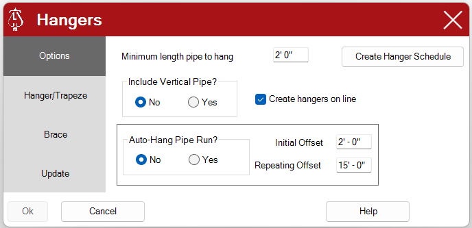
Minimum length pipe to hang
- When multiple pipes are selected to hang, any pipe with a length the same or less will no get a hanger. Exception… Picking a pipe will place hanger no matter the length.
Include Vertical Pipe?
- No Prevents hangers from being placed on vertical pipes, drops and sprigs that exceed the minimum length. (always default setting)
- Yes Will allow the hanger to be placed on vertical pipes, drops and sprigs.
Auto-Hang Pipe Run?
- When set to Yes, upon clicking ok from the Hangers tab, the user will select one side of a Pipe Run. Starting at that end of the Pipe Run, a hanger will be placed at the initial offset from that end and then another hanger will be placed at the distance specified by the Repeating Offset. IF the Pipe Run turns around an elbow, the Offset will be reset to the Initial Offset. No pipes should be selected prior to using Auto-Hang Pipe Run.
Update
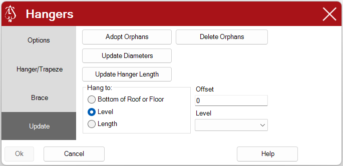
Update Diameters
- If changes were made to the pipe diameters, picking this button will update the hanger assemblies connected to the pipes in the current view.
Delete Orphans
- Deletes any hanger assemblies no longer associated with pipes that were deleted in the current view.
Update Hanger Length
- If changes were made to the length of hanger rods, this will send those changes to the project.
OK
Will add hangers to the midpoint of all selected pipes.
If no pipes were selected prior to the start of the command, you will be prompted to pick a pipe.
The hanger will be placed at the picked pipe point.
Cancel
Will cancel the command and close the dialog box.
Help
Opens this help document.
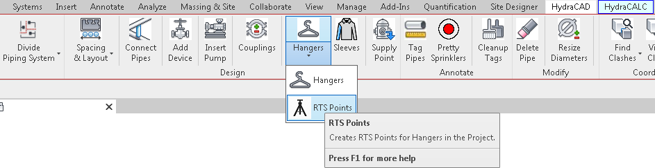
RTS Points (Robotic Total Station Points)
Robotic Total Station, often called Trimble due to that manufacturer being a market leader, is used for identifying hanger anchor points, survey control points, and architectural grid line intersections. The RTS Points function also creates a CSV (comma-separated values) file, for use with the RTS controller.
There is a 15 minute video you can watch that overviews RTS points in Hydratec for Revit, that accompanies this written help, which you can watch by using this link: RTS Points Video.
Main Dialog (3 Sections)
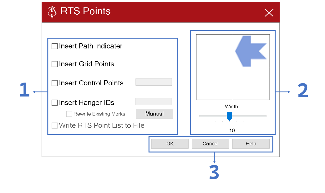
1. Operations
Insert Path Indicator:
- When checked, a control path indicator will be inserted in the active view
- The location, orientation, and size of the control path indicator will be based on the configuration defined in Section 2. Control Path Definition (see below for more information)
- A control path indicator is required to be in the active view to insert Hanger IDs and write the RTS point list to a file
- The control path indicator will determine the starting position and direction to number the hangers. The path will follow a serpentine pattern, to ensure the shortest possible path for laying out hanger points
Insert Grid Points:
- When checked, a control point will be inserted at each intersection of grid lines
Insert Control Points:
Used for survey Control Points, or user defined Trapeze and Seismic connection points- When checked, after selecting the OK button, the user will be prompted to place control points into the active view
- The text box aside “Insert Control Points” allows for entry of a prefix for what the Control Point will be labeled
- Example 1: if the entered prefix is “CP”, then the first Control Point inserted will be labeled “CP1”, the second will be labeled “CP2”, and so on for actual survey control points.
- Example 2: if the entered prefix is “TZ”, then the first Control Point inserted will be labeled “TZ1”, the second will be labeled “TZ2”, and so on for Trapeze connection points to the structure.
- Example 3: if the entered prefix is “SB”, then the first Control Point inserted will be labeled “SB1”, the second will be labeled “SB2”, and so on for Seismic Brace connection points to the structure.
Insert Hanger IDs:
Used to automatically indentify standard hanger anchor points based on their insertion point.
Note: Trapeze and Seismic Braces are not anchored to the structure at their insertion point, and therefore aren't automatically included, so the Insert Control Points function is used instead.- When checked, each hanger visible in the active view will be labeled based on the path defined by the Control Path Indicator
- The text box aside “Insert Hanger IDs” allows for entry of a prefix for what the Hanger will be labeled
- Example: if the entered prefix is “H”, then the first Hanger inserted will be labeled “H1”, the second will be labeled “H2”, and so on
- Rewrite Existing Marks:
- When checked, will allow for previously labeled Hangers to be re-labeled. If left unchecked, any previously labeled Hangers will not be relabeled.
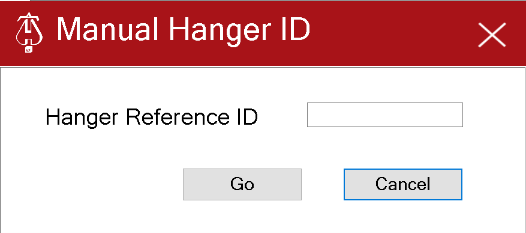
- Manual Button:
- When selected, a new dialog will open (see below) for a label prefix to be assigned. Then the user may select hangers manually to label the hangers using their own method
- Write RTS Point List to File:
- When checked, all Control Points and Hangers visible in the active view will be stored in a comma separated file in the same directory that the project is save in.
- To write a file, there are two (2) prerequisites: a control path indicator must be inserted in the active view, and the hangers in the current view must be labeled
2. Control Path Definition
Boxes:
- Click on the appropriate box to define where in the current view the control path will start, i.e. upper left, upper right, lower right, or lower left.
- Once the arrow is in the desired position, click the arrow to change the direction of the path, the arrow will alternate between either of the possible directions
Width:
- Move the slider to the left or right to select the appropriate width of the control path. This width is in feet.
- Example: if the control path arrow is in the upper right hand corner pointing left with a width of 10 feet, then the control path with start in the upper right hand corner of the active view and the hangers within the top 10 feet will be labeled moving right to left, then the control path will make a u-turn and the hangers will be labeled in the next 10 feet moving left to right
- Move the slider to the left or right to select the appropriate width of the control path. This width is in feet.
3. Buttons
- OK: when this button is pushed all checked operations will be executed
- Cancel: when this button is selected the command will cancel and the user will be returned to Revit
- Help: when this button is selected this help document will be displayed in the default web browser
Additional Help (Videos and additional resources)
For more help regarding the hangers button: click here
For more help regarding the RTS points button: click here
For other help that might be relevant to hangers: click here
For other help that might be relevant to RTS points: click here
HydraCARDs (Troubleshooting)
For HydraCARDs regarding the hangers button: click here
For HydraCARDs regarding the RTS points button: click here.
For other relevant HydraCARDs for hangers: click here
For other relevant HydraCARDs for RTS points: click here