Appearance
Insert Pump
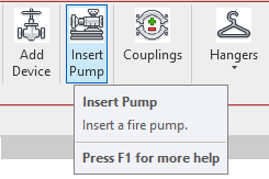
To jump to a video explaining the Insert Pump button, click here.
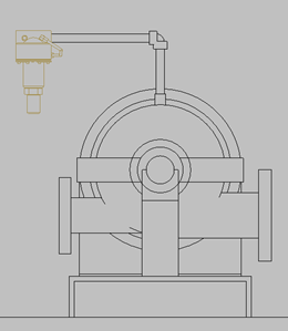
Insert Pump is used to place a pump into the currently viewed floor plan. When the insert pump button is selected, there will be many options of pump types with different makes and models.
It is recommended that before you insert the pump, that you've drawn the suction pipe up until where you'd like the pump you're inserting to be connected to.
Summary
- Draw suction pipe up until approximately where you'd like the pump to be connected.
- Click the Insert Pump button.
- Click the tab at the top of the dialog box according to what pump type you want.
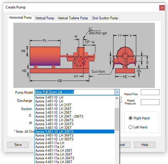
- From the pulldown list, select the exact pump you're looking for.
- Info will be automatically entered according to the pump selected.
- You can manually edit these values if need be.
- Once your pump has been selected, press 'Ok' to insert it into the floor plan.
- Once the pump is inserted, rotate the pump so its inlet lines up with the suction pipe.
- Drag the suction connector of the pump onto the suction pipe so the inlet and the suction pipe connects.
- Once the pump is inserted and connected to the suction, it can be moved horizontally and vertically to be placed on the pump pad - and the pipes will stay connected.
Example video of Insert Pump Button
How Do I Use The Button?
Draw suction pipe up until approximately where you'd like the pump to be connected.
Clicking the Insert Pump button will open the dialog box as show below.
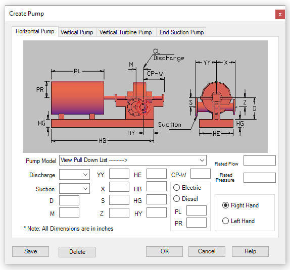
Click the tab at the top corresponding to the pump type you would like to insert into your project.
After you have selected the pump type you want, click the arrow of the pump model dropdown list which is labelled with View Pull Down List.
After selecting a pump, all the the information will be automatically entered here according to the selected pump.
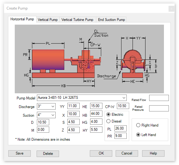
You can edit the dimensions as needed. You can also create your own pump if the one you're looking for isn't listed by manually entering the information associated with it.
Once all your selections are made, pick 'OK' to place the pump on the floor plan.
Once the pump is inserted, rotate the pump so its inlet lines up with the suction pipe.
Be sure to drag the suction connector of the pump onto the suction pipe so the inlet and the suction pipe connects. If you grab the pump from another spot it won't connect like it's supposed to.
Once it's assembled and connected to the suction pipe, the pump can be dragged around freely to sit on the pump pad.
Adding Connector to Pump
Example: Aurora 3-481-10 LH add casing relief valve
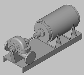
This guide explains how to add a separate connector for a relief valve to pumps that come with two standard connectors.
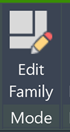
1. Edit the Pump
Select the valve and click the "Edit Family" button
Change the view to "Ref. Level" in the Project Browser
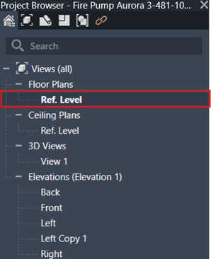
You'll now be in a top-down view of the pump
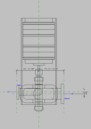
2. Create a Mounting Point
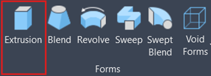
Navigate to the Create Ribbon

Select "Extrusion" under the Forms tab
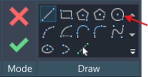
Under the Draw tab, select the circle tool to create a cylinder shape
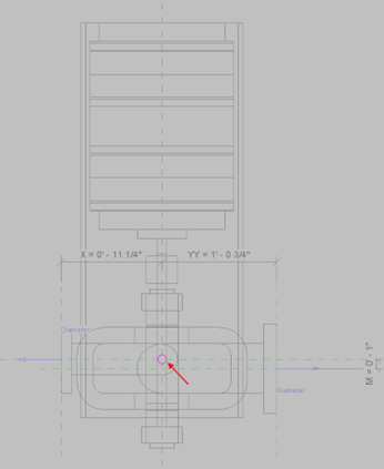
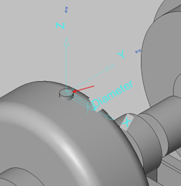
Place the circle in the center of your pump (cylinder should be ½" in diameter)
Once the circle is correctly positioned and sized, select the green check mark in the Mode tab.
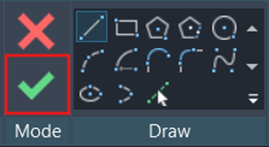
The cylinder is now placed in your pump
3. Create a Mounting Point
Leave the Ref. Level view and return to the original view
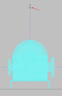
Go to a forward-facing view of your Pump.
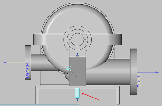
Select the cylinder and use the arrow at the top to pull it upward to the desired position.
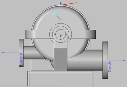
Change your view to get a good position of the top of the cylinder.
4. Add the Connector
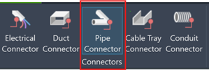
Navigate back to the Create tab
Click the "Pipe Connector" button
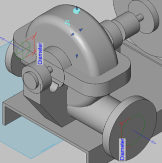
Place the connector on the top of cylinder.
Select the connector and change it to the desired size (currently ½")
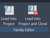
5. Load into Project
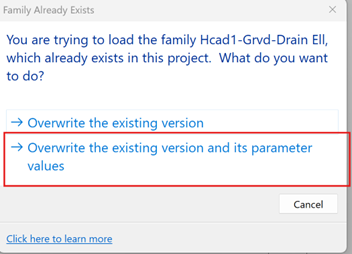
Click the "Load into Project" button
When prompted, select "Overwrite the existing version and its parameter values"
6. Add Piping and Relief Valve
Use a section view to get a good angle of the edited pump
Select the pipe fitting to draw a pipe out of the connector.
Go to "Add a device" and place a casing relief valve onto the new piping.
How Do I Add a Pump Control Box
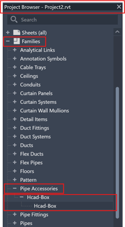
Use the Hcad-Box family to represent a pump control box.
To add one to your project...
- Go to the Properties Toolbar >Families> Pipe Accessories>Hcad-Box> Drag Hcad-Box into project.
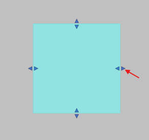
Place in the desired location of your project.
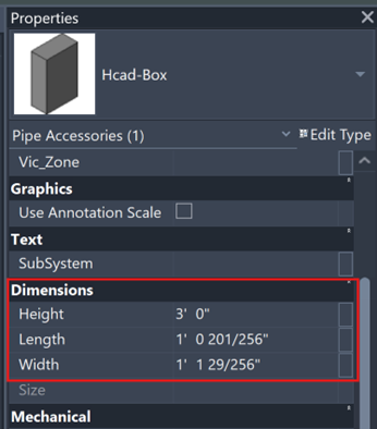
You can change the vertical location by settings in the Parameters
Use the grips to adjust the size accordingly or go to the Properties Toolbar scroll down to the dimensions and make your changes.
- You can see these changes represented in the Dimensions category of the Hcad-Box's properties.
Other options include Hose Cabinet, Pump Pads, Nito Generator, Spare Sprinkler Head Cabinets, used to note clearance spaces by setting graphics to Transparent. and so much more!
For some useful on Hcad-Box, click here
Additional Help (Videos and additional resources)
For more help regarding the insert pump button: click here
For other help that might be relevant to insert pump: click here
HydraCARDs (Troubleshooting)
For HydraCARDs regarding the insert pump button: click here
For other relevant HydraCARDs: click here