Appearance
An Explanation of the UCS
UCS is short for the User Coordinate System. Whether you draw in two or three dimensions, all lines, symbols, intersections, etc., represent points on the coordinate system. For example, when you draw a 20’ branch line 5’ from a wall, you probably think of placement in terms of proximity to the main, joists, and other branch lines. In a plan view, proximity is in terms of left or right and up or down. The importance of the UCS is not obvious or rarely used in 2D drawings. When you add the third dimension, however, proximity enters a new level and can be quite confusing at first.
The UCS has several elements, however the basic premise remains the same; that any two points can be referenced from each other in terms of up – down, left – right, and front – back. These terms are expressed as coordinates on the X, Y and Z axes.
Coordinates
If you were asked to describe the point where the riser enters the two dimensional (2D) building here, you might say that it is 3’ to the right of the west wall and 2’ up from the south wall.
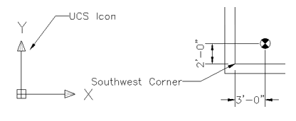
In other words, the riser is 3’ along the X axis and 2’ along the Y axis from the southwest corner. You could also describe the location of the southwest corner with respect to the riser location. You would say the southwest corner is –3’ along the X axis and –2’ along the Y axis from the riser. The proximity of the two points is described in relative terms to one another.
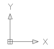
The X axis is indicated by the X on the UCS icon. The X axis contains all X coordinates as you move left or right on the line in the diagram below. X coordinates are all points that can be measured along this line.
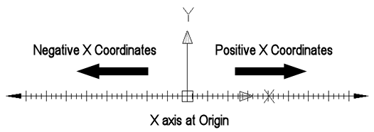
Negative X coordinates are points on the X axis to the left of the origin. Positive coordinates are points to the right of the origin. The origin is described in detail in the next section. The Y axis is indicated by the Y on the UCS icon.
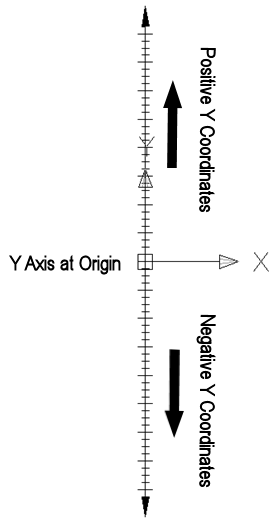
The Y axis contains all Y coordinates as you move up or down on the line in the diagram shown here. Y coordinates are all points that can be measured along this line.
Negative Y coordinates are points on the Y axis down from the origin. Positive coordinates are points up from the origin.
The Y axis contains all Y coordinates as you move up or down on the line in the diagram shown here. Y coordinates are all points that can be measured along this line.
Negative Y coordinates are points on the Y axis down from the origin. Positive coordinates are points up from the origin.
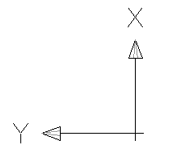
The Z axis is always perpendicular to both the X and Y axes. If the X coordinates are left and right and the Y coordinates are up and down, then the Z coordinates are pointing straight at you
The diagram below shows the Z axis running perpendicular to the X and Y axes. The UCS position was altered slightly to provide a clear view of the Z axis.
You will find additional information on the Z axis and rotating the UCS later in this section.
Origin
Another way to describe the location of the riser shown below is in terms of coordinates as they relate to the origin. The origin is the point where all three axes, X, Y and Z, are zero. In 2D drawings, the coordinate system is the template for which dimensions are calculated. For example, the absolute coordinates for the riser in the diagram below are 10’-0” , 5’-0” , 0’-0”. Coordinates are always expressed in the X,Y,Z format and are calculated from the origin. The Z coordinate is zero. 2D drawings only make use of the X and Y axes. A HydraCAD template typically has its lower left corner at the origin.
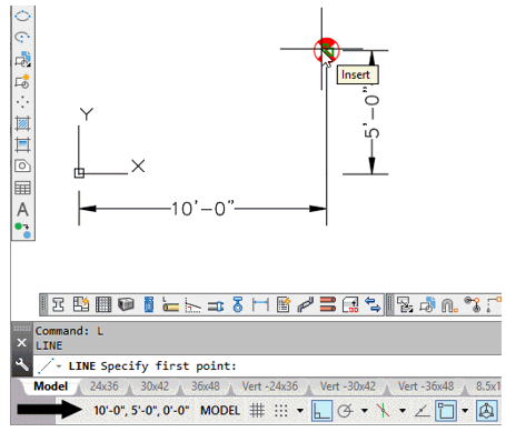
The mouse location may be displayed using coordinates on the status line as shown. The mouse pointer is positioned at the center of the riser symbol.
The square symbol is only displayed on the UCS icon when it is at the origin (0,0,0).
Units
The UCS is used in AutoCAD as a reference point. This reference point will be measured in millimeters if your drawing is set up using the metric system, or in inches when the Imperial system is selected.
Displaying the UCS Icon
The UCS Icon display options are located in the View pull down menu. A check mark next to the On option indicates that the icon is currently displayed in the main window or active viewport.
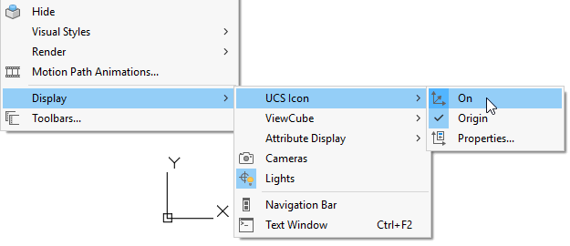
A check mark next to the Origin option will display the icon at the origin. This is only possible when the origin is within view on the main window.
Turn either option on or off by selecting them as shown here.
World Coordinate System (WCS)
Up to this point, you have seen the UCS icon displayed in its most common form using the top view. The X is pointing to the right and the Y is pointing up. The UCS icon shown here is referred to as the World Coordinate System or WCS. This is the default UCS.
As you will see later in this section, the UCS can be rotated or moved to any position. When working in 2D, you have little need to rotate, view or even worry about the UCS. This changes when you begin to draw in 3D. Drawing in 3D requires that you make use of all three axes, however, commands only function along the X and Y axes or planes. This means, you will have to rotate the UCS. The more complex your drawing, the more you will need to rotate the UCS. The WCS provides a constant reference point from which you can base your 3D operations. The WCS cannot be changed.
The UCS icon here has been rotated. Note that the origin cross has been removed from the icon. This means that the UCS has been moved from the WCS position.
You can retrieve the WCS anytime by entering UCS at the command line and selecting World. This will reset the X, Y and Z axes to coordinates 0,0,0.
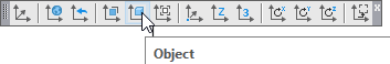
Using Object UCS to set the Working Direction
When working in three dimensions in AutoCAD you can only draw, copy or move items in a single plane.
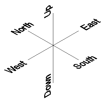
There are six primary directions and three planes in which to move in three dimensions: East-West, North-South and Up-Down. Since the drawing cross hairs can only represent four of these directions at a time, you have to reset the UCS to get the correct plane to work in.
The UCS toolbar contains many choices for setting the UCS. All of these are described in your AutoCAD documentation.
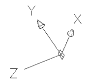
You will find that the Object command is very useful for drawing Hydratec 3D fittings. By picking existing Ski Poles, you can orient the UCS so that you can draw, copy or move objects in that plane.
When you pick a Ski Pole, the UCS origin will be set to the insertion point of the Ski Pole. The UCS positive X direction will be set to the green diamond direction. The UCS positive Y direction will be set to the red heart direction and the positive Z direction will be set to the direction of the blue spear.
The examples below illustrate this very useful command.
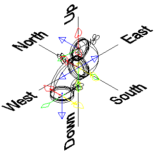
Two 90° elbows have been inserted as shown. They are connected at the North-South, East-West and Up-Down axis origin. The outlet of the right elbow is pointing North. The outlet of the left elbow is pointing down.
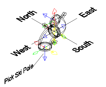
Start the Object UCS command and pick anywhere on the elbow Ski Pole that is pointing down. This resets the UCS so that the crosshairs are aligned with the club, spade, diamond and heart symbols on the Ski Pole. Now, you can easily move, copy or draw objects in the East-West and North-South directions. For example, you can start a line with a pick and then drag the mouse for direction and enter a distance for the end as you would do in two dimensions.
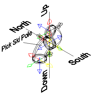
Start the Object UCS command again and pick either Ski Pole where the elbows are connected. This resets the UCS so that the crosshairs are aligned with the club, spade, diamond and heart symbols on the Ski Poles. Now, you can easily move, copy or draw objects in the North-South and Up-Down directions.
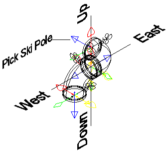
Start the Object UCS command again and pick anywhere on the elbow Ski Pole that is pointing North. This resets the UCS so that the crosshairs are aligned with the club, spade, diamond and heart symbols on the Ski Pole. Now, you can easily move, copy or draw objects in the East-West and Up-Down