Appearance
Start AutoCalc
Layer(s): HYD
Shortcut: SAC
Associated: All Calculation Toolbar Commands
Ribbon: Process Panel
Overview
AutoCalc is a routine that will extract and interpret the information in your HydraCAD drawing and transport it to HydraCALC.
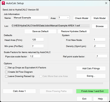
Start AutoCalcs will raise the drawing to 3D and the process dialog will appear.
Calculation Settings
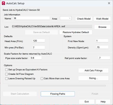
In Job Information, enter a Name for the calculation file. The area number entered will be appended to the file name. You will find the combined name in the Loc: field.
Use the Browse button to change the file location. The default is the regular HydraCALC jobs folder. You can save your new browsed location using Save as Default. The Restore Hydratec Default will bring back the original location.
Select the Area to calculate from the list. This list shows those areas that were found as tagged in the drawing, according to the instructions earlier in this chapter.
Check Model and Walk Model will check the project for errors. After clicking, pick in the Model screen and enter SME at the command prompt to open the HydraCAD Errors dialog box. Any errors found will be reported in the box.
For Head Area, enter the area of coverage for the sprinklers in this area. This area applies to all sprinklers that have not been marked using Figure Head Area. Min Pressure is the minimum end head pressure. This applies to all sprinklers that have not been marked using the Set Pressure command. Sprinklers in the remote area will be calculated according to the formula Q = K√Pt. If, during calculation, particular sprinklers need more pressure than the minimum due to the specified area of coverage, K-factor and density, HydraCALC will use the greater of the two.
The First New Node is the reference point name to begin with when AutoCalc assigns them. The next reference point will be this value plus one, and so on. Manually assigned reference points will not be overwritten by this value or by sequential values that are generated.
Density is the value in USGPM/ ft2 or LPM/ m2 for the specified area.
Adjust the Scale Factors for Pipe Sizes and Reference Points if you want them to be larger or smaller on your drawing when you return from HydraCALC.
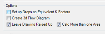
Select Set up Drops as Equivalent K-Factors if you want typical drops or sprigs to be set up as equivalent K-factors. This will save on the number of pipes in your calculation and the number of reference points on your drawing. If unchecked, each drop will be assigned its own reference points and piping.
Check Create 3d Flow Diagram if you want to produce a three-dimensional flow diagram when you return.
When you run AutoCalcs, the drawing must be converted to a 3D Model or “Raised Up” for information gathering. This can be time-consuming for larger drawings. To save time on the next run through AutoCalcs, especially when running more than one area, select the Leave Drawing Raised Up checkbox.
If you are planning to calculate more than one area consecutively right now, then check the Calc More than one Area box.
Sizing
Any pipes with a ‘?’ diameter label or no diameter at all will be dimensioned by AutoCalc via a type of pipe schedule. Any pipes with a diameter (1”, 1 ¼” etc.) will be transported intact to the HydraCALC program. In the HydraCALC program you will be given the chance to change these diameters. The final sizes agreed upon in the HydraCALC program will be returned to and updated on the drawing.
An example would be if you wanted 3” (80mm) mains but weren’t concerned about the line diameters other than that they meet the hydraulic design criteria. Here you would label all mains with a 3” tag and leave the lines undimensioned. After AutoCalc was run, the mains will still be labeled as 3” and the lines assigned diameters according to the pipe diameters specified in the AutoCalc Pipe Schedule Input. You can view and edit this table from the Sizing button in the AutoCalc Setup box. Any reference points you have added, or which were inserted by a previous AutoCalc process will be recorded and reused.
To view or edit the Pipe Schedule, press the Sizing button.
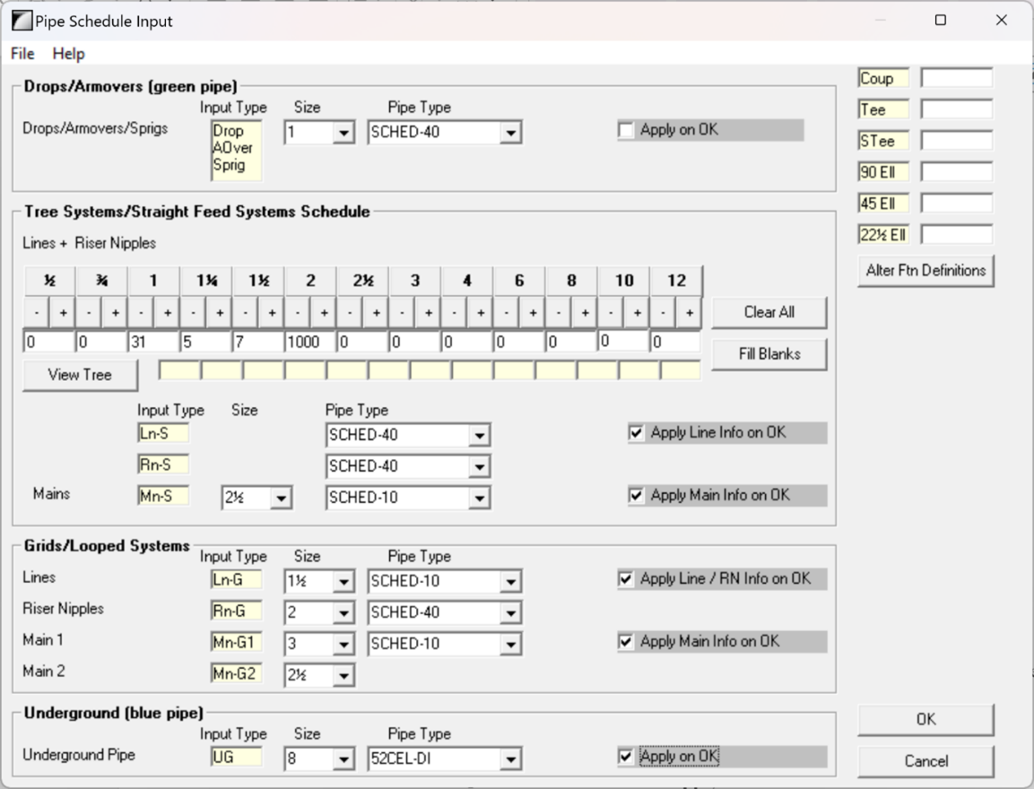
AutoCalc uses this schedule to assign sizes to pipes that do not already have sizes on them. These will be imported into the HydraCALC program. This dialog box is also available in HydraCALC to make global pipe size changes.
If a change is made to any input, the Apply Main Info on OK checkbox is automatically checked, ensuring that those changes are saved.
The top area is for Drops, Sprigs and Arm Overs, which here are set to 1” Schedule 40.
The next area is for Tree/Straight Feed Systems. The Lines and Riser Nipple schedule is shown here. 1” pipe will be used for up to three sprinklers, 1 ¼” pipe will be used for four to five sprinklers, 1 ½” pipe will be used for six to seven sprinklers, 2” will be the maximum size in the above image. You can type in the number of heads or pick the + or - to set them. Put in a large value next to the largest size you want to use in your branch lines. Above, you can see that 1000 heads are entered for 2”. This ensures that there will never be 2 ½” or larger sizes used here, unless you had already manually sized pipes as such.
Lines and Riser Nipples will be Schedule 40 and Mains will be Schedule 10. Tree mains are below this - 2 ½” is selected above.
The Grid/Looped Systems area is where to set the size and pipe type of the grid lines, riser nipples, primary main (Main 1), and floater or secondary main (Main 2).
The Underground above is 8” 52CEL-DI.
The C-Factor for the underground and all piping will be those associated with the pipe types selected. This data is edited and stored in the HydraCALC program.
More Calculation Settings
Add Calc Fittings allows you to add valves, backflows, fittings, etc to specific pipes. This information will be carried over to HydraCALC during the calculation process. For more information, see the Add Calculation Fittings topic.
Once AutoCalc has begun and you are transferred to the HydraCALC screen, you will have the opportunity to change fittings.
Running Multiple Areas
It is possible to run multiple areas through the calculation process, one after the other. These can also be run one by one by finishing each area before restarting AutoCalc. If multiple areas are set up with flowing heads; the Calc More than one Area option will be selectable. Leave Drawing Raised Up is a real timesaver in these cases, as this greatly reduces the cycle time between areas.
If only one area is to be calculated, then uncheck the Calc More than… box.
Beginning the AutoCalc Process
When you have the AutoCalc Setup box set the way you want, press Calc Area to begin the process. The number on the button is the currently selected remote area.

It will take a little while for the routine to gather and process the information from the drawing. A status bar will indicate the steps completed by the AutoCalc process:
When processing is complete, the HydraCALC program will be launched with the relevant drawing information extracted and analyzed. By this point AutoCalc has assigned reference points, sizing, fittings, and determined flow paths.
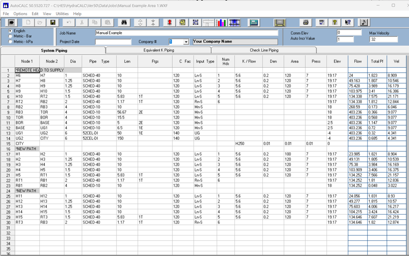
Understanding how Calculations are set up
The organization of the piping in the calculation may not always seem to make sense, but there is a logic to it.
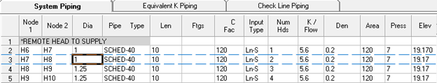
The very first ‘path’ in the calculation runs from the furthest head to the water supply. This is in keeping with NFPA13 requirements and industry practice ever since hydraulic calculations were allowed.
The next paths are the other flowing branch lines in this job. In a grid, it would be each branchline in the grid, beginning with those lines with flowing heads for the remote area on them, and followed with all the non-remote lines, from main to main.
The reference point numbering follows this same pathing, unless you assigned your own reference points. If you find the numbering too confusing, then we suggest you consider numbering it to your liking, given all the reference point tools we have.
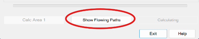
If you are confused as to exactly where a given pipe is in the system, there is a handy tool included in the AutoCalc to assist with this. Change focus back to the AutoCalc dialog and pick the Show Flowing Paths button.
This will bring up the Flowing Paths dialog. If you do not see all the piping appear in the tan part of the box, pick the Options drop down menu and pick Expand All.
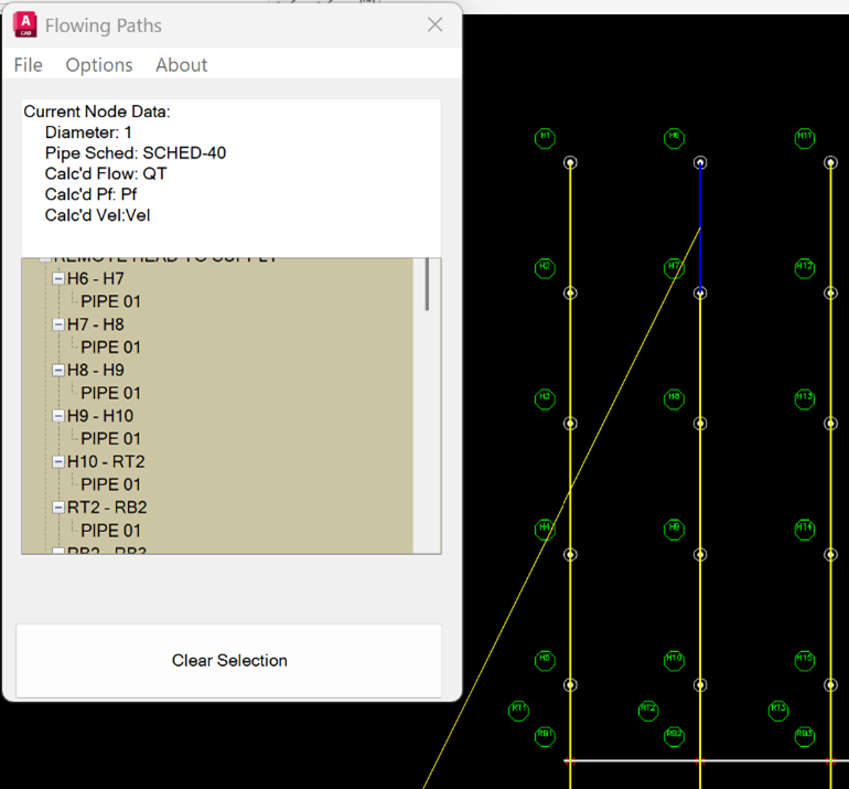
Each reference point pair is represented. You can expand the pair to see what pipes are between those points. A yellow line will point from 0,0 to the pipe(s) referenced. The pipe between the two ref points will be highlighted in dark blue. After the job has actually been calculated, the flow and other information will also be filled in.
You will also be able to see the reference points designated for this calculation and be able to match them to the pipes in the data input. If you think it will be helpful, you may want to plot this view of the drawing and have it side by side with your calculations as you complete them.
Close the dialog box by picking the X in the upper right corner to restore the Start AutoCalc dialog. Switch back to HydraCALC when you are done viewing this information.
Adjusting the Calculation Input
Before editing the input, it is important to note that certain columns are grayed out. These columns may not be edited because doing so would disrupt the AutoCalc process and cause errors upon re-entry to HydraCAD. As a rule, Reference Points may not be added, and Pipe Lengths may not be changed while you are in the HydraCALC screen. These changes will cause errors when returning to the HydraCAD drawing.
The following information is covered in great detail in the HydraCALC manual and help files.
AutoCalc has assigned reference points under Node 1 and Node 2. Think of these as the ‘from’ and ‘to’ nodes. Pipe sizes, lengths, types, C-Factors, the number of sprinklers supplied by the pipe, and elevations have all been assigned. Now is a good time to fine tune the HydraCALC input if needed, before performing a hydraulic calculation. First, check the elevation entries under the Elev column. The elevation entry will correspond to the reference number under Node 1. Move the cursor to the elevation that you would like to change and edit with the keyboard.
Next, make any pipe diameter changes that are required.
Move the cursor to the diameter field and right-click.
A box will appear where you can select the pipe type and nominal diameter.
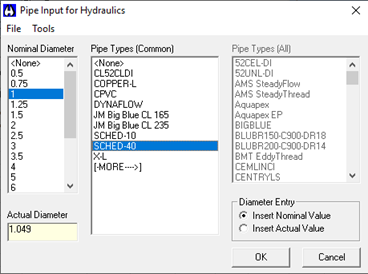
Select the pipe size and type from the lists and press OK. The nominal diameter and pipe type will be entered in the appropriate cells. When you run a calculation, the actual internal diameter will be retrieved from a database and used in the calculation.
If your Pipe Type does not appear in the list, select [MORE] to view an expanded inventory. Press OK to finish the entry.

You may need to insert valves, especially on the main system riser, if you did not earlier use the Add Calculation Fittings command. The riser, in this example, is the entry from TASR to BOR.
Move the cursor to the Fitting cell and right click.
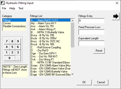
Pick from the list to add fittings to the field on the left. You can also enter a Fixed Pressure Loss or an Equivalent Length for non-standard fittings by typing in the available fields.
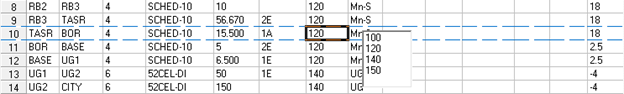
Check that your C-Factors are correct. The default is 120, however, the underground pipe and others may be different. Move the cursor to the C-Factor entry and press the right mouse button. Select the required C-Factor from the list.
Finally, you could edit the Input Type column which indicates the type of pipe in the system. Ln-S represents line piping, Mn-S main piping, RN-S riser nipples, UG underground piping, etc. The correct use of this column makes it possible to use certain other HydraCALC tools such as Find, the Graphical Pressure Display and the Pipe Schedule.
AutoCalc will automatically pick up most of the piping types such as lines, mains, riser nipples and underground. You will likely have to change the system riser since AutoCalcs will interpret it as a main.
To do this, move the cursor to the Input Type that you want to edit. Right click and pick from the available options.
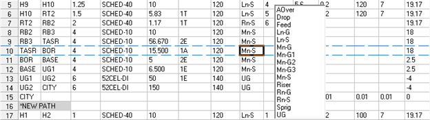
The example shows a change from Mn-S to Riser. If you have not already added a flow in the drawing by using the Hose/Added Flow button, you may want to add an outside hose allowance by right clicking in the K/Flow column and selecting from the list displayed.
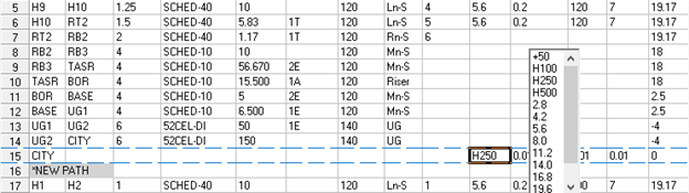
You can also type in a value. In this example, H250 is a 250 GPM Outside Hose Allowance at the CITY node.
Running the Calculation
Now, you are ready to perform a Hydraulic Calculation. To do this, press on the Calculate button as shown here.
This will display a dialog with some information gathered from the input and some options for the calculation itself.
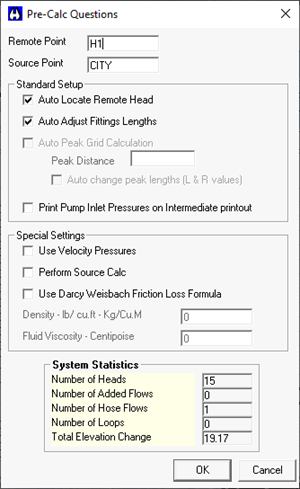
The Remote Point is always filled in with the first flowing node in a system; one that has a K-Factor or a flow. You may enter a different node if you like, but it must have a K-Factor or a flow.
The Source Point is the node that was specified in HydraCAD via the Water Supply command.
The Auto Locate Remote Head option means the program will first run a calculation using the Remote Point specified. It will then compare that head to the other heads in the calculation and, if another is more demanding, it will re-run the calculation using that other head. The most demanding head will replace the ID in the Remote Point edit field. This option is checked by default.
Auto Adjust Fittings Lengths means the program will adjust fitting equivalent lengths for non-Schedule 40 pipe as per NFPA13. Fitting lengths are always adjusted for C-Factors other than 120 as per NFPA whether this is selected or not.
Auto Peak Grid Calculation means that HydraCALC will run calculations on the remote area as if it were moved in each direction by the Peak Distance. It will continue in a certain direction if that area is more demanding than the preceding one. This distance is the typical distance between sprinklers on the branch lines. In this way, the remote area is moved over by one head in distance on both sides of the remote area. If the head spacing between heads is not typical, then the Auto Peak option must not be used.
With the Auto Change Peak Lengths option checked the pipe lengths entered in the System Piping tab will be adjusted if Auto Peaking finds a more demanding remote area. With the Auto Change Peak Lengths option not checked, the pipe lengths will not be adjusted, even if Auto Peaking finds that an adjoining remote area is more demanding. If the remote area was moved, you will need to move the remote area polyline and flowing heads blocks in the drawing. There is a utility to do this, Move Remote Area (MVA), which will be covered later in this chapter.
Print Pump Inlet Pressures on Intermediate printout. will show additional pump information in the working copy of the calculations
Select Use Velocity Pressures to use velocity pressures in your calculations. These calculations use normal pressure when determining sprinkler discharges. Under certain situations, NFPA standards may require you to use velocity pressure in your calculations.
Check the Perform Source Calc option to do a source or supply calculation. This will show you the maximum discharge density that this system and water supply can supply. Head discharges and pipe velocities will be based on the available water supply. With this option not checked, a demand calculation will be performed with the most remote head set at minimum flow and pressure.
Use Darcy-Weisbach Friction Loss Formula is to be used when Darcy-Weisbach calculations are to be performed instead of the standard Hazen-Williams formula. Selecting this option requires that you know and enter in the Density and Fluid Viscosity in their respective fields.
To find out more about this dialog box and other program features, see the HydraCALC V50 User Manual.
Press OK to perform the calculation. You will see a basic summary of the calculation.
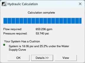
The system Flow and Pressure requirements and the pressure safety margin (cushion) in both pressure and percentage amounts when using the supplied input. The dot is green for a positive safety and red for a negative one.
Press Details to expand the dialog to show more calculation details.
To see a more comprehensive calculation summary, press the View button, which shows the actual and required flows from each sprinkler head.
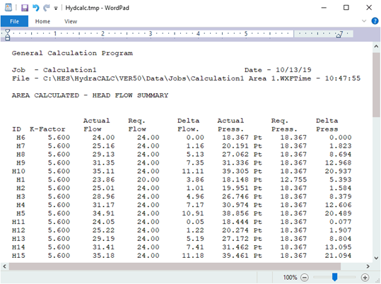
You can also see excess flow (Delta) and pressure delivered to each head in the remote area. Print this summary by using the File menu and selecting Print. When you exit the calculation summary file, you will return to the Hydraulic Calculation dialog box. Press OK to return to the HydraCALC screen.
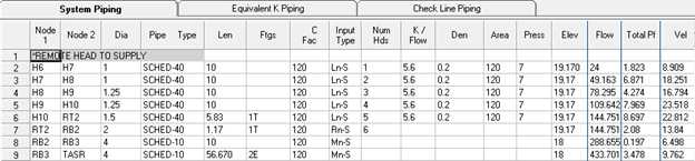
The three right columns now have values for pressure, flow, and velocity at their corresponding reference points.
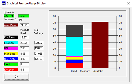
At this point, you can choose to get the system demand reasonably close to your requirements with the water supply by adjusting pipe sizes or using a different type of sprinkler head. By analyzing the sprinkler system and viewing which components are using the most pressure you can make an informed judgment as to which changes you should make.
The easiest way of doing this is to view the Graphical Pressure Display found in the View drop-down menu or by pressing the Graphical Pressure Display button.
You can make pipe changes manually or by changing the Pipe Schedule while you are in the HydraCALC program. You can then perform another calculation and view the results. The Pipe Schedule can be edited and the calculation performed as many times as needed to get the desired results. When you exit HydraCALC and return to the HydraCAD drawing, the last pipe sizes that you calculated with will be inserted into the drawing.
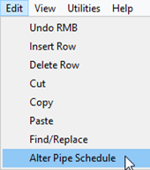
To access the Pipe Schedule, select Edit from the pull-down menu, then Alter Pipe Schedule. The same dialog box will open that was used when AutoCalc was first started.
Adjust the pipe sizes accordingly and check the appropriate Apply on OK buttons. Exit the dialog box and try another calculation.
You can also print out the Calculation Summary before returning to the drawing.
Returning to HydraCAD
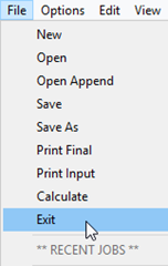
When your calculation is reasonably close, pull down the File menu while in HydraCALC and select Exit or pick the X in the upper right corner.
The AutoCalc routine will begin processing again and you will return to the HydraCAD drawing. The AutoCalc Setup dialog box will appear.
Pick the Finish Area 1 and Exit button.
The final pipe diameters that you used while in the HydraCALC program will be inserted, as will the reference points.
All pipes which had ? labels for diameters, or were not sized, will now have diameters inserted.
The reference points that either you specified or that AutoCalc added will be inserted in a white layer close to the nodes that they represent.
If you had selected Calc More than one Area, then the Finish Area 1 and Exit button would instead read Finish Area 1. You could then select a different area number to calculate from the Area drop down list and pick Calculate Area 2 (or whatever you selected) button to then calculate that area.
If you are done calculating areas (or just changed your mind after one), just select the Exit button at the bottom of the dialog to end the AutoCalc process.
HydraCARDs (Troubleshooting)
For HydraCARDs regarding Start Autocalcs: [Click Here]