Appearance
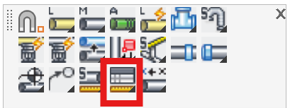
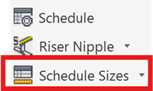
Schedule Sizes
Layer(s): SPRKDATA, SPRKDATB
Associated: Size Pipe Setup
Ribbon: Insert Panel
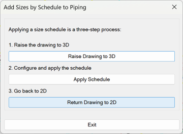
Used to size pipes according to a predetermined schedule. Pipe sizing through a schedule is a three-step process. Starting the command opens this dialog box.
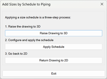
Press Raise Drawing to 3D to start. The drawing will raise to 3D.
Start the command again and press Apply Schedule. The following dialog box will appear.
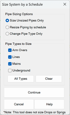
Choose between sizing unsized pipes or all pipes sized and unsized. You also have the option of only changing the Pipe Type.
Select the Pipe Types to Size. Press Continue.
The Pipe Schedule Input dialog box will appear.
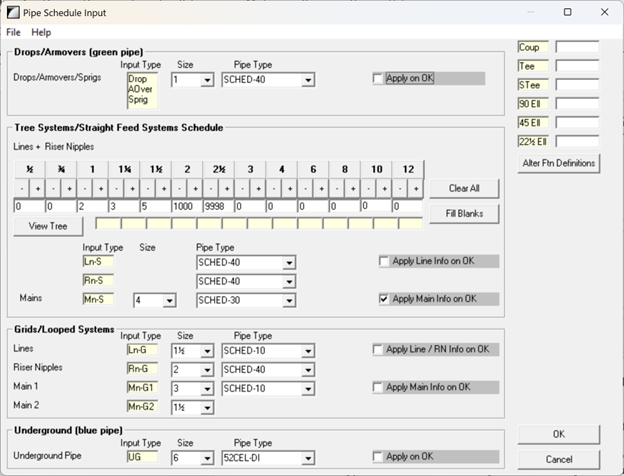
If you change any values in a section, the Apply on OK box will be checked, making sure those changes are recorded.
In the Drops /Arm Overs section, select the pipe size and type from the pull-down lists.
The Tree Systems/Straight Feed Systems area is for sizing pipes for trees or other straight feed systems. You can type in the number of heads you want sized by each diameter or press the + and - buttons to change what is there. For example, the figure shows a 2 for the 1” pipe size. This means that the first two pipes will be 1” diameter and will feed two sprinklers. A 3 is entered for the 1 ¼” size. This means that the third pipe will be 1 ¼” and will feed three sprinklers. Continue in this manner until all fields are filled. If you make a mistake, just change it. A 9998 for a number tells the program to make that the largest size to be used, regardless of what is in the other boxes after it, to the right.
To set the straight feed Mains size, select the diameter next to the Mn-S Input type. 4” is selected here.
Select the Size and Pipe Type for the straight feed lines (Ln-S) and straight feed riser nipples (Rn-S). Press Ok to exit the dialog and make the changes.
For Grid/Looped Systems, select the Line (Ln-G), Riser Nipple (Rn-G), Main 1 (primary main) and Main 2 (secondary main) Size and Pipe Type from the pull-down lists. These diameters and pipe types will apply ONLY to pipe which loops back onto itself and could possibly flow in either direction. This does not apply to the pipe which is feeding or leading to the gridded pipe.
For the Underground section, select the Size and Pipe Type from the pull-down lists.
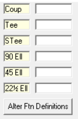
Alter Ftn Definitions allows users to apply different elbows and tees based on the pipe type selected. By default, the fittings associated with the letters C, E, T, and F, as defined in HydraCALC. Fittings associated with other letters, like those of CPVC, can be substituted in here, rather than you having to change them in th HydraCALC program manually.
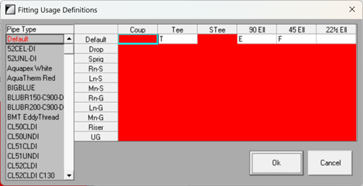
Picking Alter Ftn Definitions brings up a dialog. Clicking on the red Default Pipe Type will show where these letters come from.
For the CPVC pipe type, by contrast, the following letters are used:
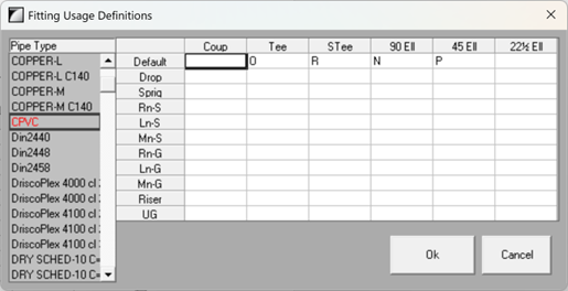
When a calculation is run through AutoCalc, it will always assign the letters T, E and F as needed. If CPVC is the chosen pipe type in the drawing/model/calculation, then the stored equivalent length values assigned to the letters O, N and P will be used instead of the stored equivalent length values for the T, E and F.
You can assign new letters to this or any other pipe type using this utility. Press Ok to exit this utility and save your changes.
Press Ok to exit the Alter Pipe Schedule dialog and apply the changes you made. You will return to the Pipe Schedule Input dialog box. Press OK to return to the drawing. You will be prompted to Pick Pipe.
Pick any pipe in the system. Start the Schedule Sizes command again and pick Return Drawing to 2D to finish.
HydraCARDs (Troubleshooting)
For HydraCARDs regarding Schedule Sizes: [Click Here]