Appearance
Main Couplings

Layer(s) affected: SPRNK2, SPRKDAT1, SPRKDATA
Alias: MC
Associated Commands: [Line Couplings]
HydraCAD Ribbon: Insert Panel
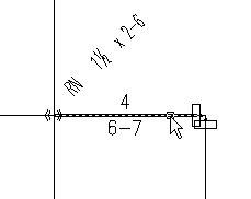
Used to insert main couplings where the pipes are connected at a specified or stock length. The example here shows a main ready for coupling insertions at stock lengths. Assume that you want the main pipes to be 12’-6” long. The couplings for the elbow at the right have already been cut in.

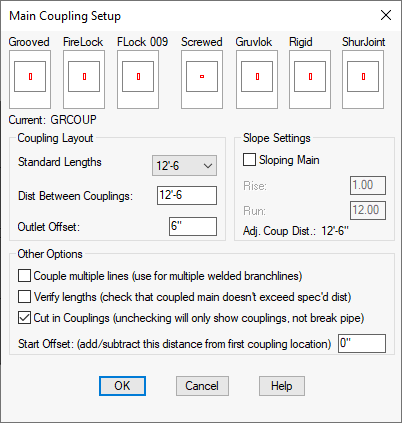
When you select the Main Couplings command, the following dialog box will appear.

Select the coupling style by picking the window for Grooved, FireLock, Flock 009, Screwed, Gruvlok, Rigid or ShurJoint. For Standard Lengths, select a distance from the list. If you want a distance that does not appear in the list, enter it in the Dist Between Couplings field.
Outlet Offset is the minimum distance that a coupling will be cut in next to a riser nipple. The default is 6” (150 mm) or enter your own value.
Select Sloping Main if your main is at an angle. Enter a Rise and Run for the slope. When you press the tab key, the Adjusted Coupling Distance will appear. This is the length that will be used for insertions.
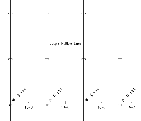
Couple Multiple Lines is for inserting couplings on a number of parallel lines. After you press OK, you will be prompted to select a Typical Line. Select a line and then select all of the lines requiring couplings. An arrow will appear pointing to the first picked line. Right click and you will be prompted to zoom out so that all of the pipes appear on the screen. Right click again and HydraCAD will show a preview of the coupling locations. Right click to insert or press Esc to exit. Continue to right click for all pipes. An arrow will appear for the current pipe.

The example here shows couplings inserted on the branch pipes at 12’-6” intervals.
With Cut in Couplings checked, the pipes will be broken at insertion points. The Start Offset is the starting distance from the end of the pipe picked. The default is 0” (0mm), or right at the end of the pipe.
Sometimes, due to rounding, the resulting pipe lengths will add up to more than the chosen distance between couplings. If you select Verify Lengths (imperial only), then HydraCAD will read all the resulting lengths and add them up. If the total exceeds the specified distance, the one rounded length which is the most different from the actual length of the pipe will be adjusted ½” downwards to compensate.
When you press OK, HydraCAD will prompt with: Please pick end of main - placement will start from the end picked …
Pick the right end of the main after the existing coupling. HydraCAD will respond with: Zoom now to get all of this main on the screen.. Right Click when ready…

All of the main sections for which you want couplings must be displayed on the screen for this command to work. It is not able to adjust when it comes to a tee, so if you have a tee in the middle of the main, zoom one half at a time or start at the tee and work back. After pressing Enter, HydraCAD will show a preview for the coupling insertions.

HydraCAD indicates the locations with green lines touching the mains. If shorter red lines are present, they indicate that less than a full length of pipe is used. Even if less than a full length was used, be assured that the Coupling Offset is being respected and that coupling will not be closer than specified. Right click to accept these locations or press Esc to exit. The drawing below shows the inserted couplings with modified pipe lengths:
*Tip* - If you do not like the coupling locations - instead of pressing Esc, consider entering No and picking the other end of the main.

*Tip* - If you do not like the arrangement of the couplings as specified by HydraCAD, consider using Custom Coupling to put a coupling at a convenient location (perhaps ½ the main stock length) and start Main Coupling from there.
HydraCARDs (Troubleshooting)
For HydraCARDs regarding Coupling Setup: [Click Here]

 HydraDOCs