Appearance
Tagging Example 9

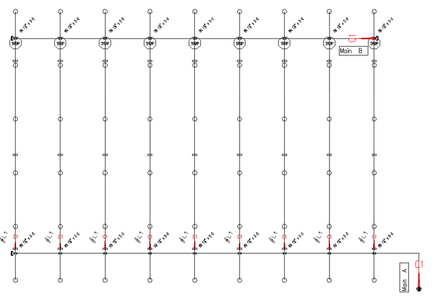
Tagging a grid with welded mains and welded lines with threaded riser nipples, threaded starter pieces and threaded “outriggers”
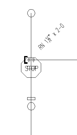
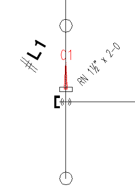
For this type of grid system, tagging usually requires one tag per main and one Stop sign for each grid line, as well as tags for each welded branch line.
1. Follow either Example 1 or Example 2 to tag mains as Welded/Grooved.
2. Insert a Stop sign at the couplings on each line closest to the far main. Use the Line Couplings command to insert a Stop sign and coupling on each line.
3. Tag lines as Welded/Grooved and place the Listing tags on the couplings closest to the near main.
4. Define Drop or Sprig elevations with DefLines.
The example here is a typical grid. The mains have been tagged as _A (Space A) and _B (Space B). Couplings have been inserted one foot away from each riser nipple on both sides to accommodate the connection between the threaded and grooved pipe. Grooved couplings have also been cut into the branch lines using the Line Couplings command at 21-foot intervals, starting at the couplings on the near main side.


Each branch line will be tagged with one line tag with a Listing Tag ID of L1. The riser nipples, starter pieces and outriggers will get listed and numbered automatically. Since they reside outside of the listing tags and Stop signs, they will be listed as threaded with cast iron fittings (the default). The branch lines within the listing tags and Stop signs will be listed as welded and grooved.


 HydraDOCs