Appearance
Setup
Layer(s): HANGERS
Shortcut: HS
Associated: Insert One Hanger / Steel Hang / Auto Hang / Lay Out Hangers / Trapeze / Cap and Hang
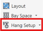
Ribbon: Insert Panel
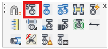
Choose hanger type, length, method of calculation, and insertion options.
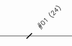
A hanger consists of:
- a tick mark indicating the hanger location on the pipe
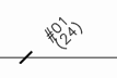
- a type indicating the hanger style (example #01 or #07B)
- a length from the point of hanger attachment to the building (such as top of steel), to the centerline of the pipe. The length can also be shown as the cut length, or rod length.
Note: All hangers are inserted as center-to-center lengths. After AutoList is run an additional hanger with the cut length will be inserted for each center-to-center original.
Note: No hanger command spaces hangers according to NFPA 13 nor does any hanger ‘know’ where the next hanger is. Placement is solely up to the designer.
The Hanger Setup dialog box controls hanger information.
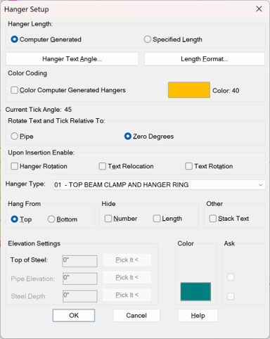
Hanger lengths can be either Computer Generated or User Supplied; or a combination of both. The recommended setting in most cases is Computer Generated. This means rod lengths are calculated from the building (TOS, Floor) and pipe (AFF, BTS) elevations. It is particularly useful for sloping steel and/or sloping pipes.
Computer Generated hangers will initially appear with a length of 0-0. This length (the center-center length) will be updated once the drawing is elevated to the 3D Model (S3D) and subsequently returned to the 2D Model (S2D).
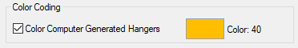
You have the option to Color Computer Generated Hangers so that they can be easily differentiated from User Supplied ones and you may choose the Color for that as well.
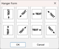
Hanger Text Angle is used to set the text angle of the hanger. Select your preferred option and pick OK.
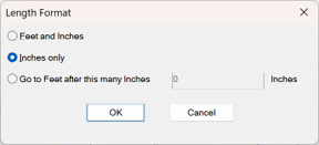
Length Format refers to how US rod lengths are displayed, unit-wise. The choices are:
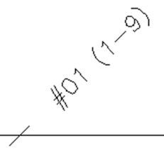
- Feet and inches - length will always appear in feet-inches, such as ( 2-0 ).
- Inches only - length will always appear solely in inches, such as ( 24 ).
- Go to Feet after.., - length will be changed to feet-inches after the specified number of Inches.
Tip - Some users enter their standard rod or stud length as the value in the Go to Feet… field.
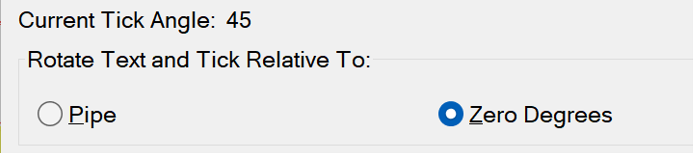
Hanger text and tick marks are inserted at 45 degrees relative to the ‘normal’ X-axis and Y-axis, by default. They can, however, be rotated relative to the pipe via the Rotate Text and Tick Relative To: setting. This is useful when the pipe is drawn at an angle, so that the tick marks are seen clearly.
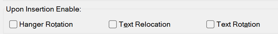
As hangers are inserted you can control the Hanger Rotation and Text Rotation. You can also choose a new text location with Text Relocation for every hanger insertion, using the mouse.
The Hanger Type list is extracted from the hanger assembly part of the HydraLIST database. You can create or modify these assemblies within HydraLIST- see the HydraLIST manual for further information. The number to the left of the description will appear in the hanger tag.

Hang From indicates hanging from the Top or Bottom of the structural members. ‘Steel’ is a general term that can also mean concrete or wood joist.
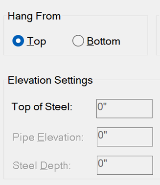
With Top, the depth of steel or similar will have no bearing. The c-c hanger length will be determined by subtracting the Pipe Elevation from the Top of Steel elevation.
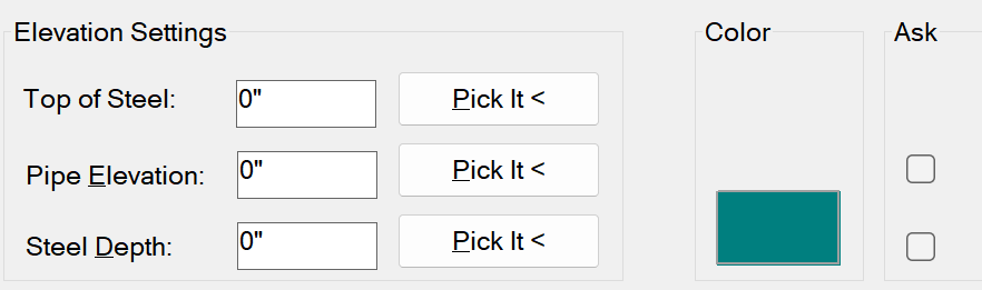
With Bottom selected, the Steel Depth field will become active. The c-c hanger length will be calculated by subtracting the Steel Depth and Pipe Elevation from the Top of Steel elevation. Hanger lengths that use the Steel Depth are colored for clarity. The swatch next to this item can be used to set the color.
When Specified Length is selected, the Top of Steel and Pipe Elevation settings become active.
Enter the Top of Steel, Pipe Elevation and Steel Depth in the appropriate fields. You can also use the Pick It < buttons to pick elevation blocks to extract values from. A list of these blocks appears below.
Relevant elevation block:
TOS (TOP) Structure Elevation
AFF/BTS (AFF) block
Size Steel (SSZ) block
If you check the Ask boxes, you will be prompted for the elevation before each hanger is inserted.
Tip - If you know exactly how long the hanger (say, 1 foot), you can ‘cheat’ and enter the Top of Steel as 1’ and the Pipe Elevation as 0. This will give you a center-to-center length of 1’.
Tip - If you previously inserted steel depth blocks using the Size Steel command on the Steel toolbar, you can pick those to set this value.
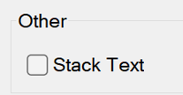
With Stack Text checked, the hanger length will be displayed below the hanger type as shown here.
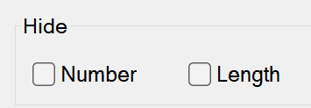
Use the Hide options to simplify hanger tag text. Number will hide the hanger type label and Length will hide the length tag. These values are still entered into the hanger blocks; you just cannot see them.
Tip - If you want to hide or show these values later, you can do so by picking the HydraTools->Modify->Attribute->Hide Attribute command (HAT).
Hanger tags have type and length attributes that are read by AutoList. The ring/clamp sizes, which are dependent on the pipe size on which they are attached, are not recorded in the hanger tag but are interpreted by the AutoList process. All hangers are gathered and calculated will appear in the HydraLIST stocklist in the Hangers section.
HydraCARDs (Troubleshooting)
For HydraCARDs regarding Auto Hang: Click Here