Appearance
Creating 3D Fittings
After you have used HydraLIST to create a list of components for your 3D drawing, return to HydraCAD and select the Miscellaneous tab in the Insert Fittings dialog box. You may notice a red, missing fittings warning and that some components have three asterisks (***) in the Quantity from .HLF column. There are no 3D drawings available for these components. You can either return to HydraLIST and retrieve replacements or produce 3D drawings for these components.
Auto Fitting Creation
Most components can be created quickly and easily using the Auto Fitting Creation routine. This command is accessed in the Utilities tab of the Insert Fittings dialog box. Creating complex or uncommon components may require you to use the 3D Fitting Builder and/or AutoCAD commands. See Utilities under the Inserting Fittings portion of the Creating 3D Fittings section of this manual for more information on using this command.
Using the HydraCAD 3D Fitting Builder
HydraCAD’s 3D Fitting Builder helps you to create your own 3D components. There are five fitting types or shapes available in the 3D Fitting Builder dialog box: Ell, Tee, Cross, Reducer and Coupling. You can use any of these shapes as they are or modify them to produce more complex 3D drawings. The name of the drawing file will correspond to the part number of the fitting.
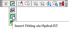
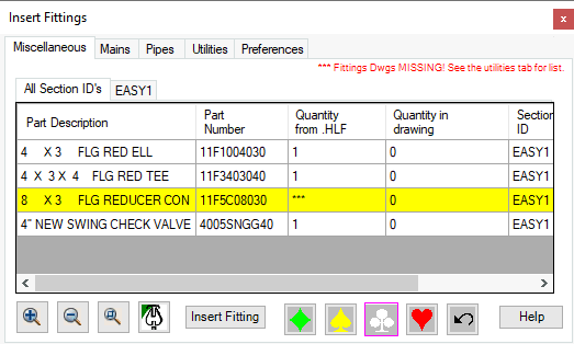
Open the Insert Fittings dialog box to access the 3D Fitting Builder. There are no 3D drawings available for any of the components listed that have three asterisks in the Quantity from .HLF column. The REDUCER has no 3D drawing in this example.
It is good practice to attempt to build simple components using the Auto Fitting Creation routine in the Utilities tab prior to using the 3D Fitting Builder.
Since the REDUCER used in the example is newly created, it does not have an associated 3D drawing file and is not in the database. Therefore, the 3D Fitting Builder must be used. Select any part with asterisks in the Quantity from .HLF column and press Insert Fitting to access the 3D Fitting Builder. Take note of the Part Number. This Part Number originates in HydraLIST and the 3D Fitting Builder will create a drawing file using this number as the filename.
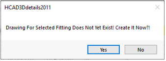
You will be prompted by HydraCAD to create the fitting. Press Yes to access the 3D Fitting Builder or No to cancel the command.
There are five tabs. Select the one that corresponds to the fitting drawing that you are trying to create. The Reducers tab is shown here.
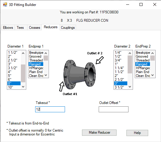
There are directions for entering the Take Out and Outlet Offset cells in the bottom left corner of the window. Enter a value in the Outlet Offset cell if you are building an eccentric reducer.
If you press Make Reducer, HydraCAD will produce your reducer. You will return to the Insert Fittings dialog box where you can insert the reducer in the usual manner.
If a fitting is created incorrectly, you must delete the associated drawing file from the 3DFTGS folder before attempting to create the fitting again. The name of the drawing file will correspond to the part number of the fitting.
Editing 3D Fitting Builder Drawing Files
The 3D Fitting Builder produces drawing files. If you are using the fitting builder to create a basic shape that will be used as a starting point for more elaborate components, you will need to locate and open the filename for editing.
Creating Basic Shapes
If you select a component from HydraLIST that has no matching drawing file, the Quantity from .HLF column will contain three asterisks in the Miscellaneous tab as shown below. As an example, a 4” Swing Check Valve (part number 4005SNGG40) is shown below.
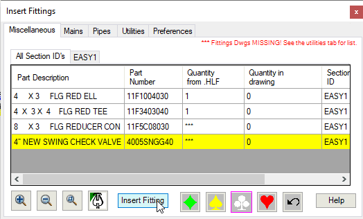
If you choose to create your own 3D drawing for this component, select it from the list and press the Insert Fitting button.
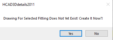
You will receive a warning message and the dialog here will appear. Press Yes.
When in the 3D Fitting Builder dialog box, select the tab of the basic shape that most resembles the component you are creating.
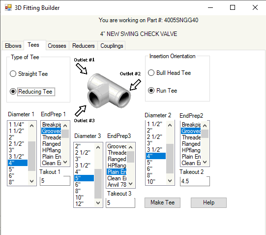
Use information from the manufacturer’s cut sheet to enter dimensions for your basic shape. The more precise you are here, the less editing you will need to perform later.
When you have entered all information required for the basic shape, press the Make Tee button. HydraCAD will produce your basic shape and place it in the 3D drawing folder.
You will return to the Insert Fittings dialog box.
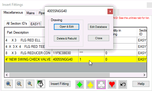
If you would like to manually enhance your 3D component, right-click with your mouse over the check valve as shown above. The dialog box above will appear.
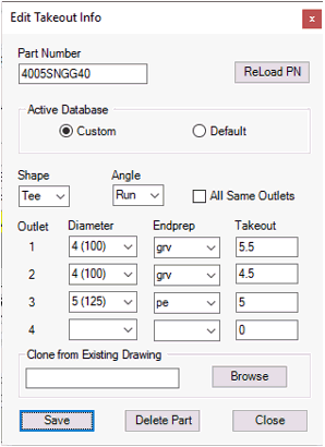
Pressing Open & Edit will open the drawing in AutoCAD where you can further enhance the drawing. Pressing Edit Database will open the Edit Takeout Info dialog box will open where you can change some of the database criteria for the part. It is intended to be a more efficient way of adjusting existing takeout information. When you have adjusted the settings, press the Save button and Close the box. When you have returned to the Part dialog box, press the Delete and Rebuild button to redraw the part with the new take-outs (as an example).
When in the Edit Takeout Info dialog box, you also have the option of cloning a part by browsing through your existing parts. For example, you may have invested a large amount of time to draw an alarm valve. In this way you can use the same alarm valve 3D drawing for different manufacturers. If both the takeout information and “clone from” information are provided, the clone information takes precedence.
Use the Delete Part button in the Edit Takeout Info dialog box to delete parts from the database as well as the 3D drawing for the part.

 HydraDOCs