Appearance
Tools sub-menu
The Tools sub-menu has a few drawing-wide tools.
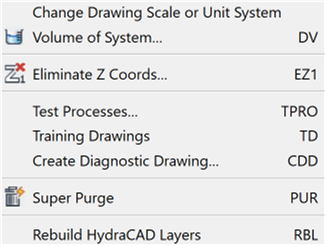
Change Drawing Scale or Unit System will open the Drawing Setup dialog box where you can make changes to the scale or unit system of the existing drawing.
When converting between Imperial and Metric, the cut lengths are not converted. To show the cut lengths in the new system of units, erase them and run another stocklist.
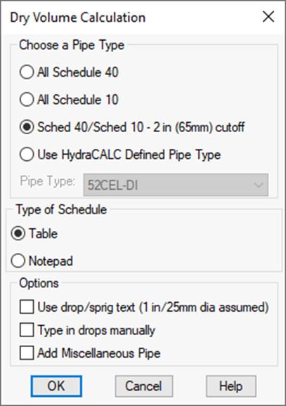
Volume of System: Opens the Dry Volume Calculation dialog box.
Select your pipe type with the radio buttons. Use HydraCALC Defined Pipe Type will display a list of all the pipe types defined in the HydraCALC program.
The command extracts all of the pipe lengths and diameters that you pick and calculates the volume of the pipe. Only the pipe sizes will be selected so you can use a window if you want to. You will be asked if you want to count drops and miscellaneous other pipes. You will have to enter diameters, lengths and quantities.
A Table will be generated listing the pipes by diameter, volume and lengths. You can also copy and paste the Notepad text into the drawing if you like.
Eliminate Z Coords: One way to eliminate Z coordinates from a drawing in preparation for use with HydraCAD. Follow the prompts.
Tip - If neither of these gives you the results you want, try the AutoCAD FLATTEN command.
Test Processes: A Diagnostic tool for testing the Pretty Pipes, AutoCalcs, and AutoList program routines. HydraCAD inserts a well-tested sample drawing into the editing area and opens the appropriate toolbar. Pick the routine to be tested from the toolbar. If the Sample Drawing works OK, you know that HydraCAD is working properly.
Training Drawings: Starts the File Open command and navigates to the Training Drawing folder. These drawings are more advanced than the test processes drawings and can be used for HydraCAD Training.
Create Diagnostic Drawing: If you have a drawing which will not work with the automated routines and you need our help, create a drawing with this button, Zip it down, and send it us.
Super Purge: Purges any unused default layers or blocks from architectural drawings in preparation for use with HydraCAD.
Rebuild HydraCAD Layers: Rebuilds the default HydraCAD layers, including linetypes and colors. Useful if layers have been purged.
Import and Export sub-menus
The Import and Export sub-menus have tools to bring in background drawings from other sources and to make drawing-wide alterations to comply with submittal requirements:
The Import flyout provides several options for changing drawings created in other programs so that they can be used with HydraCAD. You must first start a new HydraCAD drawing using one of our templates. Then, insert the drawing to be converted and run the conversion. Run through once to get a report with the different types of sprinkler heads that were defined in that drawing and cancel the conversion. Then define a like number of sprinklers using HydraCAD. After this is completed, you can run the conversion a final time.
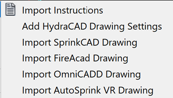
Import Instructions opens a file describing how to import various formats.
Add HydraCAD Drawing Settings changes a regular AutoCAD drawing into a HydraCAD drawing as if you started using a new HydraCALC template and then inserted your other drawing into it.
The Export flyout provides options to modify your drawing to be compatible with other applications.
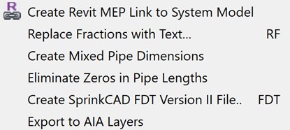
Create Revit MEP Link to System Model: Will create a Revit model (Revit required) from an AutoCAD model. Refer to the Collaborate chapter of this manual for more information.
Replace Fractions with Text will convert HydraCAD pipe size, length and riser nipple blocks into text.
Create Mixed Dimensions will show both metric and US units for pipe sizes. This only works for metric drawings.
Eliminate Zeros on Pipe Lengths will eliminate leading and trailing zeros from pipe lengths. For example, 0-9 will become 9 and 1-0 will become 1. The new lengths will be placed on the CHANGED_TEXT layer.
Create Tyco FDT File will create a file that can be opened and calculated in SprinkCALC with the FDT option.
The pipe to be exported must be sized. There must be a water supply, at least one flowing head tagged using the Operating Sprinklers command. The drawing should be raised to 3D before executing.
Start the command.
A message is displayed after launching.
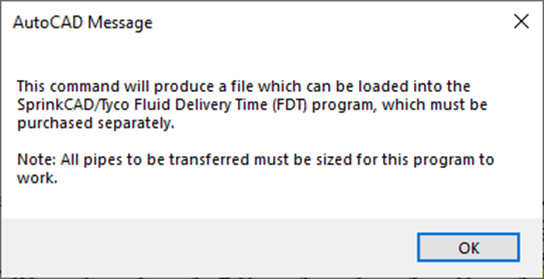
Press OK.
The dialog box here appears.
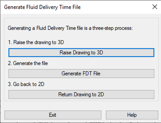
If the drawing is not already elevated to 3D, pick 1. Raise Drawing to 3D. You will need to restart this command after the drawing is raided in this manner.
Otherwise, pick 2. Generate FDT File.
This displays the Calculation dialog.
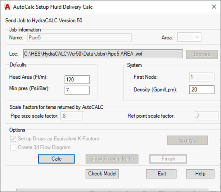
None of the settings here affect this process, so pick the Calc button.
If you get an error message, the most probable cause is un-sized pipes. You can cancel the process and size them; otherwise, proceed and fix those pipes in the Tyco program.
If there are no errors, the Save As dialog box will appear.
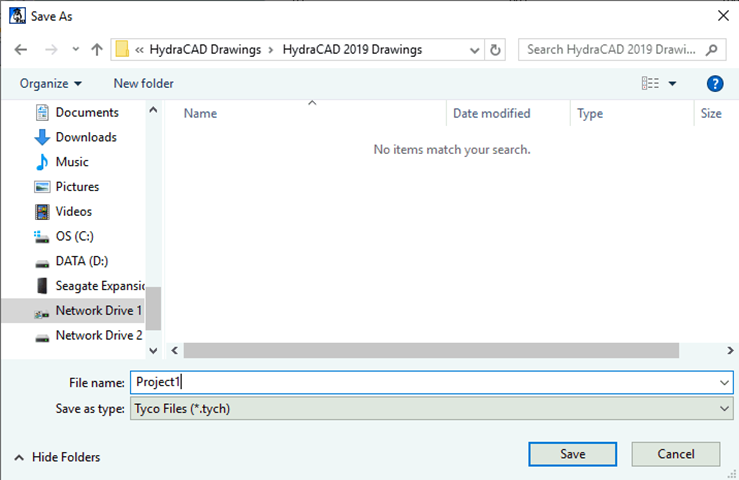
Choose a location and give the file a name.
The file will have the tych extension.
You will get a message stating that you are creating a new file and are given the opportunity to copy the header data from a file you have already created.
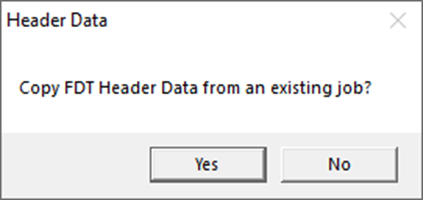
Select Yes to input Header Data from the existing job.
Select No to open the following dialog box where you can fill in the appropriate information.
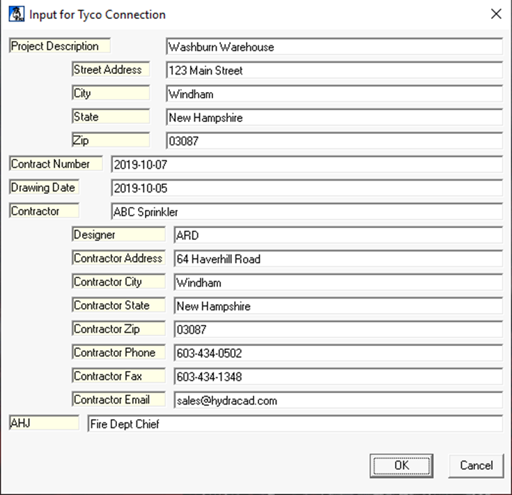
Press OK to finish.
A message will appear indicating that the file was created.
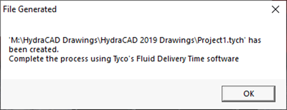
You should now be able to open the file in SprinkCALC.
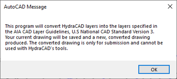
Export to AIA Layers will produce a U.S National CAD Standard Version3 layer compliant drawing.

 HydraDOCs