Appearance
Structural Layout

Layer(s): STEEL, STEEL[2,3], DMNS
Shortcut: GL
Associated: Steel Columns / Beams / Joists / Size Steel / Top of Steel
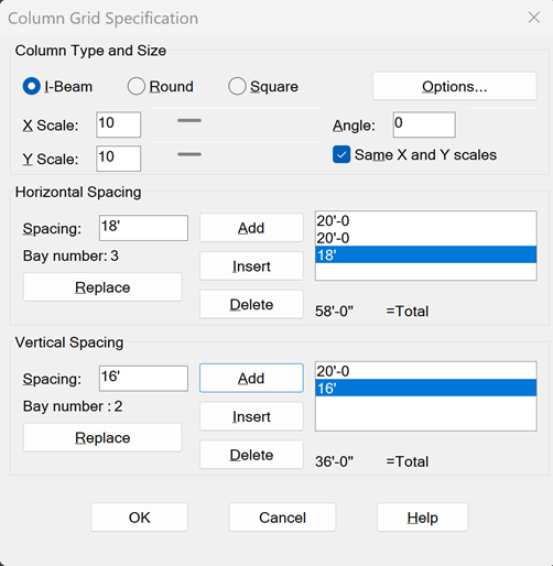
Opens the Column Grid Specification dialog box. Pick the appropriate Column Type. The Column Size, and Angle of insertion with respect to the building grid, is set with the scroll bars.

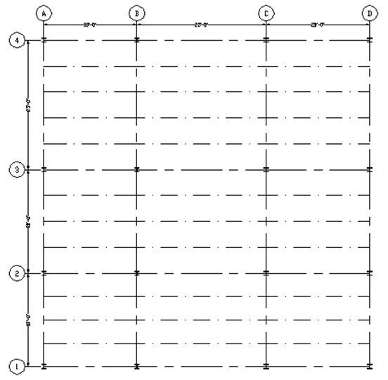
The lower sections of the dialog box are used to specify sizes and quantities of Horizontal and Vertical grid lines. Use the Add, Insert, Delete, and Replace buttons to create a sequence of vertical and horizontal bays of any dimension. The first entered horizontal lines begin at the left side of the building. Subsequent entries are added to the right. Vertical bay entries start at the bottom of the plan view and move up.
After the desired setup, press OK. Pick a point in the drawing screen for the bottom left corner of the building.

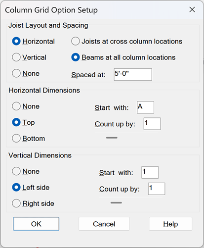
The Options… button displays the Column Grid Option Setup dialog box. The top section controls joist layout and spacing. The bottom section specifies the criteria for grid labels.
With Joists at cross column locations selected, joists will be inserted along the entire length of the grid and beams will run in the opposite direction. With Beams at all column locations selected, beams will be placed in both directions.

With Beams at all column locations selected, beams will be inserted at every grid intersection in both directions.
HydraCARDs (Troubleshooting)
For HydraCARDs regarding Structural Layout: [Click Here]

 HydraDOCs