Appearance
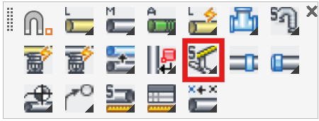
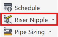
Riser Nipple Setup
Layer(s): SPRNK2, SPRKDATA
Shortcut: RS
Associated: Insert One RN / Multiple RNs / Tee w/ Riser Nipple / Edit Riser Nipples
Ribbon: Insert Panel
Set specifications for riser pipes that are inserted with most riser nipple commands, including the Insert One RN, Multiple RN’s and Tee w/Riser Nipple commands.
Settings
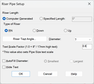
Riser nipple lengths can be Computer Generated (recommended) or User Supplied. If User Supplied, you would have to know and enter the Riser Length in the appropriate field.
If you select Computer Generated, the riser nipple lengths will be determined automatically by the system model. Computer generated riser nipples are displayed with a magenta circle around the red ‘clamshell’ riser nipple symbol.
If you select Riser Text Angle… this dialog box will appear.
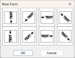
These are the available directions for the riser pipe labels. Pick one and press OK.
You also have the option of selecting a Diameter or you can leave the diameter as a ? (question mark) if you want to have it assigned during the AutoCalcs routine.
If you want the program to read the diameter from the adjacent pipes for the riser nipple, use AutoFill Diameter. The option Largest or Smallest tells the program which one to use if there are different pipe sizes where the riser nipple is to be inserted.
The Text Scale Factor controls the size of the riser nipple text. This setting also controls the pipe size text height, so be aware of the implications of changing this.
Note - The diameter of the riser nipple circle/clamshell can be set in the 3D Model Options (3MO) command on the 3D Modeling toolbar.
If you check Hide Text, no riser pipe text will appear on the drawing. This is commonly used with return bends.
Tip - You can use Hide Attributes (HAT) at any time to ‘turn off’ or ‘turn on’ the diameter and/or length of any riser nipples.
Inserting
Select the Type of Riser:
- For a main or line that changes elevation use Up or Down.
- For a main-line intersection use RN
- For a line-line intersection with an elbow or tee at the top use Up
- For a line-line intersection with an elbow or tee at the bottom use Down
If you select RN or Up the fitting will be attached to the top of the pipe. If you select Down, the fitting will be attached to the bottom of the pipe. Always choose Up or Down with respect to the direction of water flow from the supply up to the heads.
Tip - To edit a Riser pipe after you inserted it, simply double-click on it. See the [Edit Riser Nipple] command for more on this.
Example:
Select Riser Nipple Setup. The Riser Pipe Setup dialog box will appear. Select the options as shown above and pick OK.
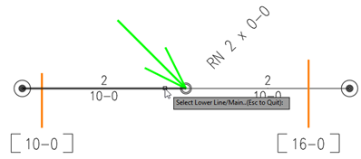
Pick the junction of two or more pipes. Depending on the arrangement of the pipes and whether you had chosen RN, Up or Down, you may be prompted to select the higher or lower pipe next to a temporary green arrow. Do so.
Or pick any point along a pipe to insert the riser nipple. This will break the riser nipple into the pipe at the exact location chosen. Again, you may be prompted to select the higher or lower pipe.
For example:
Pick the pipe somewhere between the midpoint and the end where the riser pipe was inserted.
When you toggle from Go to 3D mode to Go to 2D mode, the riser length will be updated as shown.
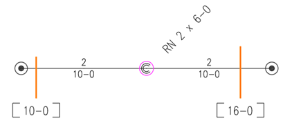
Note: A Specification elevation is required on both sides of the riser pipe when its length is set to be Computer Generated from the Model.
The magenta circle around the ‘clamshell’ indicates that this riser nipple’s length is Computer Generated.
Tip - You can use the Tracking command on the HydraCAD Utilities toolbar to ‘steer’ to a specific point along a line or main.
HydraCARDs (Troubleshooting)
For HydraCARDs regarding Riser Nipple Setup: [Click Here]