Appearance
3D Flow Diagram
Layer(s): HydraPipes, HYD2, TEXT
Associated: Start AutoCalcs
Produce a 3D piping model showing reference points and flows.
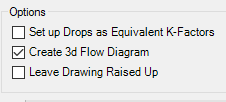
Note: you must have checked Create 3d Flow Diagram before running AutoCalcs in order to create the 3d file.
When you start the command, the following box will appear:
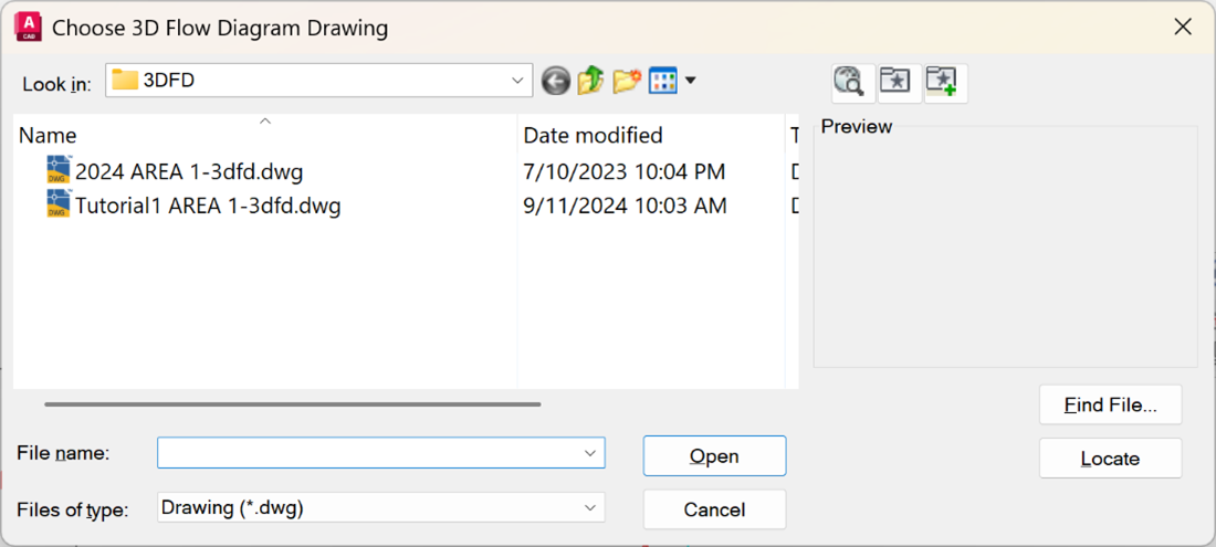
Select your file and open it. The filename will be the same as your drawing with –3dfd added to the end.
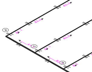
This model will show reference points and pipe flows. You can do what you like with this drawing, as it is not connected to the calculation itself once it is created. So, you can move congested items for clarity or change the view.
HydraCARDs (Troubleshooting)
For HydraCARDs regarding 3D Flow Diagram: [Click Here]