Appearance
Rotating Objects
You can rotate Ski Poles and Objects using either the blue spear or yellow spade symbol as a reference point.

Spin along Blue Axis Alias: SAB
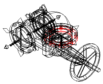
For example, the gate valve here is inserted incorrectly. The valve should be pointing up rather than to the side.

Select Spin along Blue Axis from the Build 3D Risers toolbar to rotate the object to its proper position.
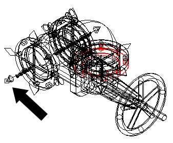
First, pick a Ski Pole as a reference point for the rotation.
Pick the Ski Pole on the gate valve as shown. The Ski Pole origin (center) will be the point of rotation.
Next, you will be prompted at the command line to select an object. Select either the same Ski Pole again or any portion of the gate valve.
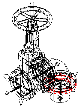
The gate valve will be rotated counterclockwise.
Flip towards Yellow Spade
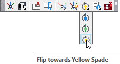
You can also rotate a Ski Pole or object using the yellow spade symbol as a reference point.
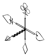
Components are inserted in the direction indicated by the blue spear symbol. The Flip towards Yellow Spade command will rotate the blue spear to the existing position of the yellow spade. When a Ski Pole is attached to an object, both the object and the Ski Pole will rotate.
Select Flip towards Yellow Spade from the Build 3D Risers toolbar.
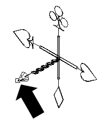
Next, select any location on the Ski Pole. This will ensure that the Ski Pole origin is used as the rotation point. The Ski Pole origin is the point where all five symbols intersect.
You must now select an object or objects to rotate about the origin. Select the object to be rotated. In this example, the Ski Pole was selected. You will be prompted at the command line to enter a rotation angle in degrees. This will be the number of degrees to rotate the object from the original blue spear of the original Ski Pole picked towards the yellow spear of the original Ski Pole picked.
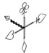
For this example, 90 was entered. The blue spear is flipped to the previous location of the yellow spade symbol as shown.
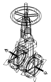
An object can also be moved. For example, the gate valve with Ski Poles shown here can be rotated with the same technique.
Select Flip towards Yellow Spade.

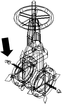
Select the Ski Pole that will be used as the rotation point as shown. The Ski Pole origin will be used as the pivot point.
Next, select any portion of the gate valve or attached Ski Poles to indicate that this is the object to be rotated.
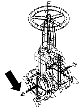
The blue spear symbol will move to the yellow spade location. The object and the other Ski Pole also move with the changed Ski Pole.
Flip towards Green Diamond
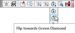
Flip towards Green Diamond is similar to the Flip towards Yellow Spade command. You can rotate a Ski Pole or object using the green diamond symbol as a reference point.
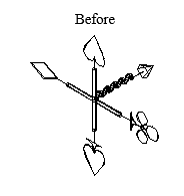
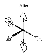
Components are inserted in the direction indicated by the blue spear symbol. Flip towards Green Diamond will rotate the object from the blue spear direction toward the green diamond Ski Pole by the number of degrees specified. The example above was rotated 180°.
Utilities is the fourth tab on the Insert Fittings dialog box as shown here.
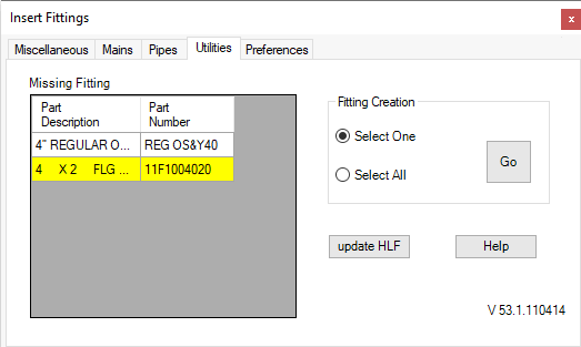
The Utilities tab has two functions: creating simple 3D fittings and updating your HydraLIST (HLF) file. The Fitting Creation section of the dialog box allows you to specify one or all missing fittings.
Create a single 3D fitting by choosing the Select One radio button. Select a single part from the Missing Fittings list and press Go to create the fitting. HydraCAD will search the parts database for the takeout information required to build the fitting.
Choose the Select All radio button to have HydraCAD attempt to build all components displayed in the Missing Fittings list. Again, press the Go button to begin the operation. When you have completed all 3D components, the Missing Fittings list will be empty.
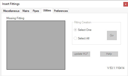
HydraCAD may not be able to automatically produce complex fittings.
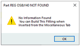
You will be prompted by HydraCAD when such a component is not created.
You can create these components using the 3D Fitting Builder and/or AutoCAD commands. See Creating 3D Fittings for more information.
The Update HLF button allows you to instantly update your HydraLIST file to reflect the quantity of 3D fittings inserted in your riser detail. Only items listed in the Miscellaneous tab are updated. Pipes and Mains will require manual updating.
When you have completed your 3D Riser, return to the Utilities tab and press the Update HLF button.
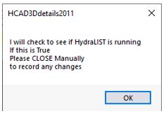
HydraCAD will prompt you to close HydraLIST. Press OK. If you are running HydraLIST, close the application. HydraCAD will examine your 3D detail and update the HydraLIST file for every instance of discrepancy between the quantity in your drawing and the quantity selected in HydraLIST.
The Preferences tab is the fifth tab on the Insert Fittings dialog box.
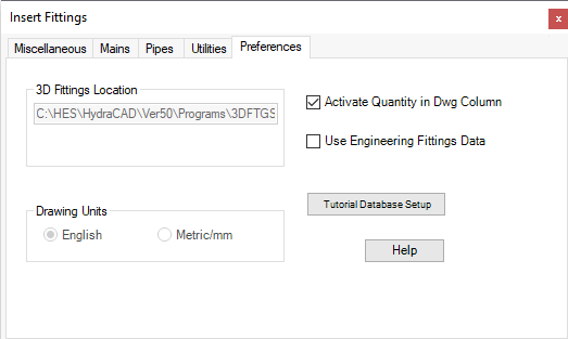
The 3D fittings drawings path will be located in the 3D Fittings Location.
In the Utilities tab, you can press the Update HLF button to update all quantities in the HydraLIST file to match the quantity in dwg column in the Miscellaneous tab. The Update HLF button updates HydraLIST immediately when selected. Alternatively, you can select the Activate Quantity in Dwg Column check box. Rather than a single update, each time you insert a 3D fitting, HydraCAD will re-evaluate the quantity in your drawing and compare it to the quantity listed in your HydraLIST file.
You may want to leave this unselected on larger jobs to speed up drawing activity. When this option is selected, the program will examine your entire drawing to determine the required quantities. For large jobs, use the Update HLF button when your drawing is finished.
Check Use Engineering Fittings Data if you have the Engineering Package, which does not include HydraLIST. With this package you must use the pre-built ITF files for valve and fitting data.
Before starting the tutorial, select the Tutorial Database Setup button. This will ensure that your tutorial will run according to the instructions.
3D Fitting Builder Drawing File Location
The 3D Fitting Builder uses the Part Number as the filename. As you produce new fittings with Auto Fitting Creation or the Fitting Builder, the drawing files will be placed in your 3D fittings folder. The 3DFTGS folder is the default directory, however, you should verify the location in the Preferences tab in the Insert Fittings dialog box. You can open these files directly from the Insert Fittings dialog box as shown in the Creating Basic Shapes section above.

 HydraDOCs