Appearance
FSC Setup

Layer(s): HCAD-FSC, HydraPipes
Shortcut: FSC
Associated: Select Sprinkler / FSC Insert
Ribbon: Insert Panel
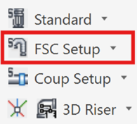
Flexible Sprinkler Connections (FCSs) are unique in the sprinkler industry and have many special characteristics. They have these characteristics stored in their ‘definitions’. These Definitions are created with this tool. Once these definitions have been created, then ‘regular’ sprinkler heads that already have been inserted can be assigned one of these definitions.
There are five steps to this process as shown in the dialog box.
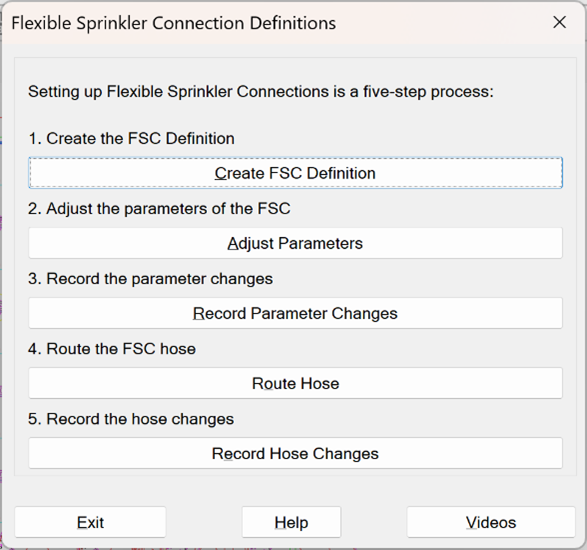
1. Create FSC Definition
Pick the first button to display the FSC Definition creation tool.
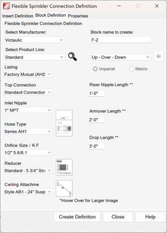
The Block Definition tab is used to select and specify the different aspects of the Flexible Sprinkler Connection. Most of the inputs are pull-down lists of manufacturer options.
Hovering over a graphic expands it to greater detail:
The Block name to create is automatically incremented as new definitions are made. This ‘name’ is a label that will appear next to the sprinkler heads you assign to it. You may enter your own to override this value.
Select Configuration (Up – Over – Down, as seen here) is used to specify the physical arrangement of the FSC. If a manufacturer’s FSC is to be used in more than one configuration, a new FSC Definition must be created as well using a unique Block Name.
Up to four fields will appear in the Select Configuration item depending on the configuration. Enter values as they apply to your FSC.
The Select Configuration (+) button to the right can be used to derive the above information directly from the drawing.
The configuration, Riser Nipple, Armover and Drop Lengths (if they are present) will be read from the head you are asked to select.
Three caveats apply:
- The head you are selecting must be in a Drop position. Uprights cannot be selected.
- The head you are selecting must have been elevated at some point so that the riser nipple and drop lengths can be determined.
- The armover must be drawn in the Armover layer (SPRKDAT4).
When you are done, select the Create Definition button and pick a location on the drawing for the Definition block:
2. Adjust Parameters
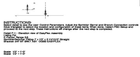
Now that the Definition Block is inserted, it is time to make some adjustments. You can restart the FSC Setup command (FSC) and pick the second button or simply select the detail to see the User Control Parameters.
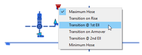
As this detail is a Dynamic Block, you can pick the blue triangles on the Sprinkler Barrel and Branch Connection to choose from a list of defaults.
You also have the opportunity to edit the Branch Location and the Branch Height.
3. Record Parameter Changes
After you make the selections, double-click on the Instructions to record the parameter changes.
As an alternative, to can also restart the FSC Setup command (FSC) and pick the third button - Record Parameter Changes.
You will be prompted to pick the Instruction notes (not the drawing detail). Once you do so, the detail and instruction text will change.
4. Route Hose
You can restart the FSC Setup command (FSC) and pick the fourth button and follow the instructions or proceed as follows:
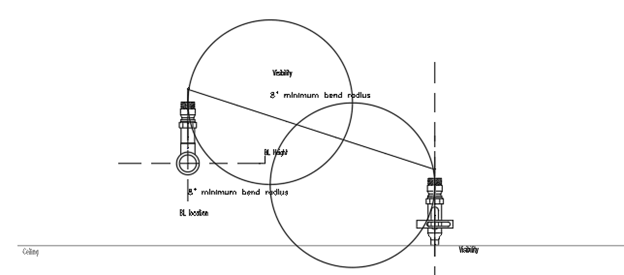
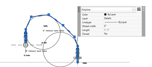
The circles drawn near the Sprinkler Barrel and/or Branch Connection show the minimum radius the hose can be bent to. These circles can be moved as needed. If and after this is done, select the white polyline pre-drawn from the Sprinkler Barrel and/or Branch Connection. Then, select the grips to shape the hose to clear the minimum radii circles.
Note To observe how long the hose is you can use AutoCAD’s Quick Properties feature, provided you customize it a bit. To do this, make sure the Quick Properties button appears on the status bar and is turned on as shown.
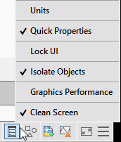
Select it if it is already there and if not activated, to turn it on. If you do not see the button, pick the Customization button at the far lower right corner of the status bar.
Select Quick Properties. This will place a check mark next to it, and the button will appear on the status bar.
Now that the button appears, and is turned on, select the white polyline. This will cause the Quick Properties popup to appear. Pick the CUI button at upper right.
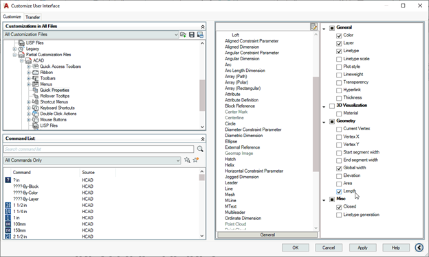
Now, check the check box next to the Length property. From now on, when you select a polyline, the length will be shown. Now, you can route the hose. Manipulate the hose shape until you reach a manufacturer’s stock length.
5. Record Hose Changes
After you route the hose, double-click on the Instructions to record the parameter changes. As an alternative, you can restart the FSC Setup command and pick the fifth button - Record Hose Changes.
Once again, you will be prompted to pick the Instruction notes (not the drawing detail). Once you do so, the detail and instruction text will change.
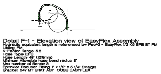
The instructions will be removed, and the hose drawn following the route you chose.
If this configuration is a new one on your computer, you may see a screen similar to the one here:
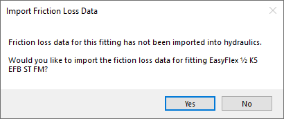
This means that new entries have been added to the HydraCALC database so that the FSC can calculate properly.
In rare situations, the equivalent length table of the FSC may not be found. The table will be created but all the equivalent lengths will be set to a large value (150 ft) so that the loss stands out and gets the user’s attention. This default value can be changed.
This completes the definition.
HydraCARDs (Troubleshooting)
For HydraCARDs regarding FSC Setup: [Click Here]

 HydraDOCs