Appearance
Remote Area
Layer(s): REMOTE_AREA
Shortcut: CA
Associated: Operating Sprinklers / Room Area / Pline
Ribbon: Process Panel
Create a polyline border in the REMOTE_AREA layer which will surround the operating sprinklers. The dialog box below will appear:
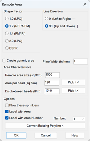
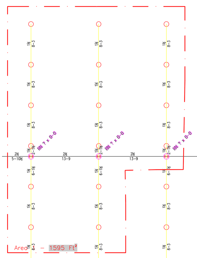
The Shape Factor is used to specify the dimensions of the remote area box. The length of the box, which is parallel to the branch lines, must have a dimension which is 1.2, 1.4, etc. times the square root of the sprinkler coverage area, according to which authority is approving the design.
For Line Direction, select 0 if the branch lines are running parallel to the X axis. Select 90 if the branch lines are running parallel to the Y axis.
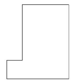
Create generic area will create a simple rectangle with dimensions dictated by the Area Shape entry regardless of the actual sprinkler head spacing. You can change the shape with grips later if you like. Use this if your head coverage area varies between heads.
The Pline Width can be entered.
Enter the Remote area size in the available field.
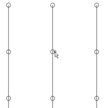
A typical head area can be entered into the Area per Head field or use Pick It < to calculate a head area from the drawing. Select a sprinkler that is surrounded by other sprinklers inside the remote area. Then, pick the sprinklers around this sprinkler with a window. The calculated area of the sprinkler that you picked first will be returned. The Dist between heads field will be changed to suit this head as well.
The Dist between Heads value can also be entered at the keyboard, or you can use Pick it <.
If you use the Pick It < button, and pick a line between two sprinklers, the length of the line will be taken as the distance between the sprinklers. If you pick a sprinkler, you will be prompted to select another sprinkler. Pick the next sprinkler to the right or above first.
The distance will be calculated, based on the line direction, and entered as the Dist between Heads value.
If the heads are of a different spacing or you want more control over the head area used, then use the Figure Head Area command explained later in this manual.
If you would like to automatically activate the sprinkler heads located inside the Remote Area polyline, select Flow These Sprinklers. Do not select this option if you expect to manipulate the shape of the remote area polyline a great deal.
To insert text that denotes the actual Area covered by the remote area polyline, select Label with Area.
To place text that denotes the Area Number, select the Label with Area Number and choose the area number (1-9) from the adjacent pull-down list.
When the box is set up, press OK.
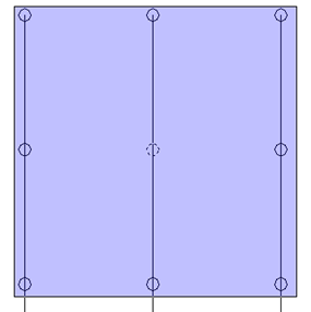
A remote area box will appear with the specifications provided.
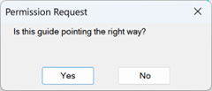
A dialog box will also appear asking you if the remote area guide is pointing the right way. Press No to mirror the shape or press Yes to place it.
Move the box to the desired location on your drawing so that the sprinklers within the remote area are surrounded and pick to insert. A dialog box will appear displaying the remote area size and that size will be added to the polyline as text.
An alternate method for producing the remote area box is to draw your own AutoCAD Polyline around the sprinklers within the remote area. The polyline must be closed for this to work. Check the Convert Existing Polyline option. You will be requested to pick this polyline when you exit the dialog box.
If Flow these sprinklers was checked in the Remote Area dialog box, the Operating Sprinklers command will start automatically allowing you to specify your flowing sprinkler criteria. Please review that command for further instructions.
Tip - If you chose the Label with Area option the value in the Area text is dynamic. If you stretch or otherwise change the area contained within the polyline, execute a REGEN command to see the updated area value.
HydraCARDs (Troubleshooting)
For HydraCARDs regarding Remote Area: [Click Here]