Appearance
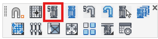
Select Sprinkler
Layer(s): SPRNKS
Shortcut: SSP Associated: All on this toolbar
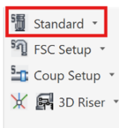
Ribbon: Insert Panel
Set the drawing symbol and sprinkler criteria for sprinkler insertions.
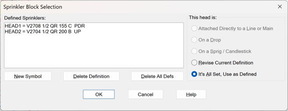
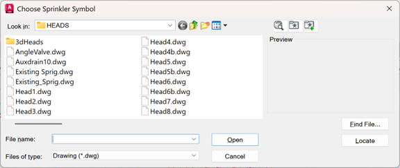
When you pick Select Sprinkler, the Sprinkler Block Selection box will appear. If you have already defined sprinklers, they will appear in the list on the left. If you want to change the specifications, select one from the list, select Revise Current Definition and press OK. To define a new sprinkler, press the New Symbol button. The Symbol Selection box will appear. Pick any ‘Head.dwg’ or ‘Side.dwg’ from the list and press OK.
The Sprinkler Block Selection box will appear again with your new sprinkler displayed at the top.
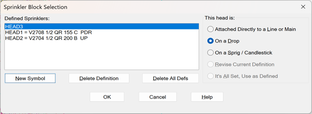
Select whether it is Attached Directly to a Line or Main or is used On a Drop or On a Sprig. Press OK and the Block Definition box will appear.
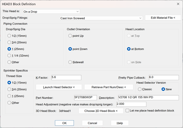
Here is where you will input more data about these sprinklers.
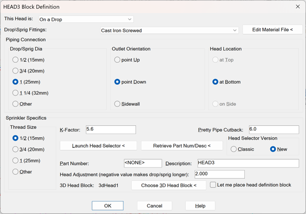
The selections at the top of the box are for defining the fittings that the sprinklers will be threaded into.
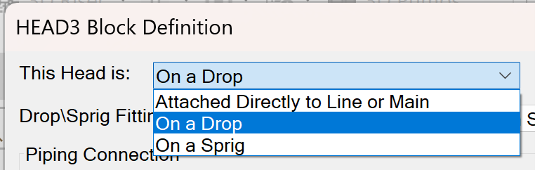
This option is automatically selected based on your previous choice for the This Head is: option on the previous screen. It should not be changed unless you are changing the use of an existing sprinkler head.

The next field defines the material type of the drop or sprig. Options here include other material types. The field is not active if the head is to be directly connected to the pipe. Edit Material File opens a text file where you can edit the options from the list
The Piping Connection area allows selection of pipe size, outlet orientation or direction and head location. The Pipe Size pertains to the drop or sprig size. The Outlet Orientation and Head Location are automatically filled out based on the previous choice for sprinkler use. Certain options are only available if they apply to the configuration (i.e. Drop / Sprig / Direct Connection) chosen.
If you have a sidewall head, there are two ways such a head can be set up. If the sidewall is attached directly to the side of a main or line (no riser nipple) then choose an Outlet Orientation of Sidewall and a Head Location of Sidewall. If the sidewall head is attached directly to the top or bottom of a riser nipple, then still choose an Outlet Orientation of Sidewall, but choose a Head Location that matches the configuration you desire.
The next area is for Sprinkler Specifics. Choose sprinkler thread size and K-Factor. The K-Factor will be used by the AutoCalc process.
The Pretty Pipe Cutback pertains to the distance that polylines are trimmed back to this type of sprinkler head in that process (i.e. most heads have a radius of 6 in / 150mm). If you have set up a sidewall the Pretty Pipe Cutback will automatically switch to 0.0. If you have created your own sprinkler heads and drew them other than a 6 in / 1500mm radius, then enter your custom value here.
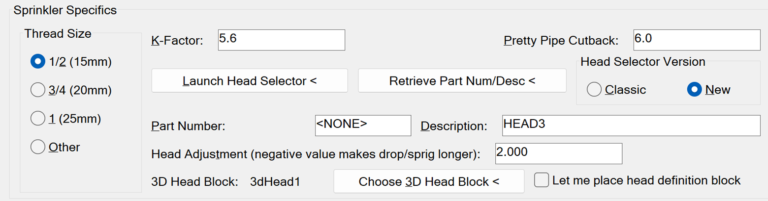
The Head adjustment relates to the takeout (positive or negative) of the head in relation to the drop. This is greyed out in this case, since this head is not set up on a drop or sprig (candlestick).
Lastly, the 3D Head Block pertains to the graphic used when the model is displayed in 3D. Picking this will open a dialog box where you can choose a representative head.
The Head Selector Version has a classic version and an online version. Here we use the New option.
Ensure that all other specifications are the same as what is shown above and press the Launch Head Selector button
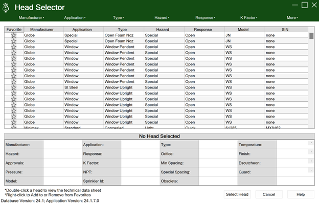
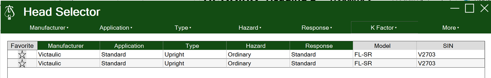
When you press on Choose Part Number <, the Head Selector will appear. This program allows you to sort through a large sprinkler database by filtering criteria. The filters are along the top of the dialog box.
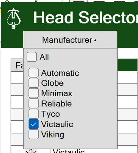
Next, Pick a Manufacturer.
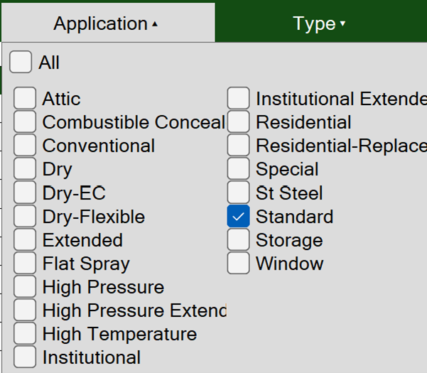
Pick a Application.
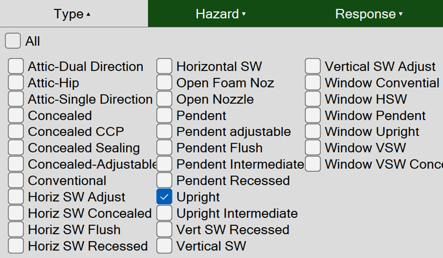
Pick a Type.
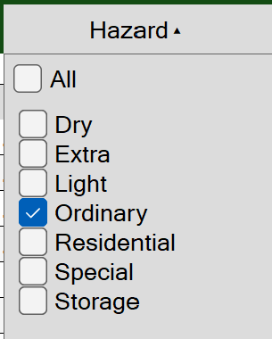
Pick a Hazard.
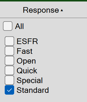
Pick a Response.
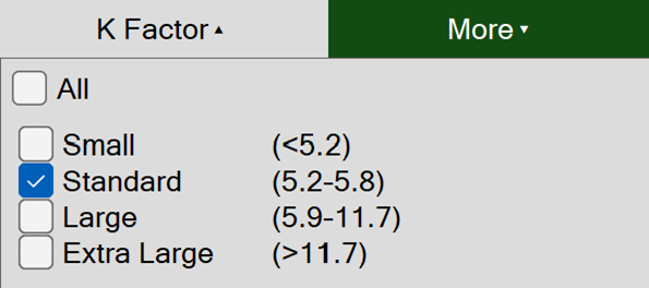
Pick a K-Factor.
Only a few sprinklers will remain in the list.
Click on the first one, and you will see the bottom portion fill out.
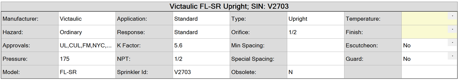
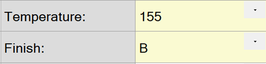
Notice the two light yellow drop lists to the right. Click on the Temperature drop list and select 155 (degrees). Click on the Finish drop list and pick B (Brass).
You can double-click on a head to view a PDF of the sprinkler head technical data sheet. You can right-click on it to add it to Favorites.
Press Select Head to return to HydraCAD.
Pick Retrieve Part Num/Desc to bring your chosen head information into the Head Setup dialog.
The Head2 Block Definition dialog box will reappear with the sprinkler information added.
Note: You may also just scroll through the list of available heads and select the one you want, or use a combination of scrolling and filtering
This information is used by the Head Schedule, HydraCALC, HydraLIST, Pretty Pipes, RevitLink and Bundle PDFs commands, among others.
The Description and Part Number will now appear in their corresponding boxes.
Press on OK to return to the drawing.
Note, when you have specified the data for a sprinkler, HydraCAD places the information in a block and places it in the bottom left corner of your drawing. It is in the ACC1 layer which is normally locked and invisible. DO NOT ERASE THIS BLOCK.
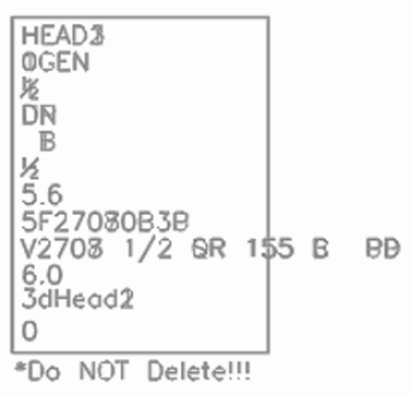
The hydraulics and stocklisting routines require this information when examining the drawing.
Tip - If you commonly use the same head types from drawing to drawing, open up your default template and define the sprinkler heads in that template. In this way, your common heads will be defined each time you start a new drawing.
HydraCARDs (Troubleshooting)
For HydraCARDs regarding Select Sprinkler: [Click Here]