Appearance
Trimble Total Station
A file may be generated by the Create 3D Hangers routine to control a Robotic Total Station (Trimble) for the purpose of laying out hanger points on a job site. A Robotic Total Station is typically comprised of three components. These three components are:
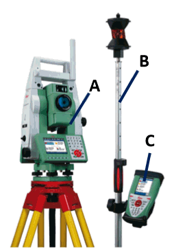
A. A surveying device mounted on a tripod. This is the actual robotic total station and is capable of 1.) optically measuring angles very accurately, 2.) digitally measuring distances very accurately and 3.) wirelessly transmitting and receiving information from the controller.
B. An optical prism mounted on a mobile pole / tripod. This ‘stick’ is used to identify to location of known points (sometimes called benchmark or control points) as part of the setup process and is used to identify desired points (hanger location points) as part of the operation of the layout process.
C. A mobile wireless controller. This smart phone or tablet sized device is used to direct the motion of the total station. This is the device that the CSV file is loaded into. It has a user interface where the operator directs the setup and use of the layout process.
The overall process can be summarized in the following steps:
• The design process is used to create a 3d model of the entire sprinkler system. That model includes the layout of all hangers, seismic connection points and set control or benchmark points.
• The 3D Hanger routine is used to generate the CSV file of Trimble Points and also to create an annotated drawing identifying those points. The job is usually broken up into smaller sections of floor area which relate to construction scheduling. One of the features of the Trimble point creation process is the specification of a starting point number (1000, 2000, 3000, etc.) so that it is easy to distinguish between various files that relate to pour sections.
• The CSV file and the associated drawing are delivered to the Trimble machine layout operator. The layout operator then downloads the CSV file to the controller.
• The CSV operator choses an appropriate position to set up the tripod so that as many hanger points may be seen as possible.
• Once the location has been chosen, the tripod is set up, stabilized and leveled. The precise 3D location of the station is established through control points.
• Once setup, the operator can select any desired hanger point to locate through the controller. The mobile prism pole is moved to the location.
As an example, start HydraCAD and open the HydraTools > Tools > Training Drawings > Generating a Hanger Point List for Use with Trimble Stations.dwg
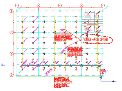
Start the 3D Hangers command.
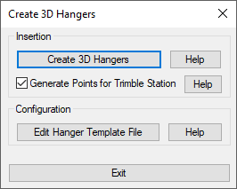
Check Generate Points for Trimble Station. Press Create 3D Hangers. The CSV file will be formed as the 3D Hangers are created.
Select your desired hangers by picking or with a window. Press Enter to finish the selection.
The User Specified Rod Size dialog box will open.
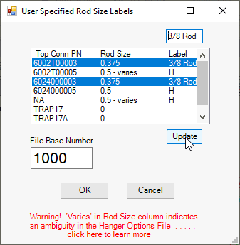
Enter a File Base Number to differentiate this file.
In the list box, any Top Conn PN (top connection part number) that ends in 03 is a part number for a 3/8” device so, hold the Control (Ctrl) key down and select all of the PNs that end in 03 as shown. Then, type into the text box at the top the label you would like to associate with those PNs (3/8 Rod is shown here).
Then, press Update and that label will be permanently associated with any of those hangers.
This process should be repeated for the PNs that end in 05 and could be labeled as ½ Rod.
If a future project includes new hanger types that have not been defined here, you will need to repeat this process to include them in your labeling scheme.
Press OK and you should be able to retrieve your CSV file from the same folder as your drawing.
The file can be transferred to a Trimble Total Station controller by connecting the Total Station Controller directly to the computer (with a USB cable) or with a USB thumb drive or by using the Trimble controller e-mail function. Any desirable layout view can also be transferred to the Trimble controller by exporting that view to a .dxf file format and transfer the dxf file to the controller in the same fashion as the CSV file.
HydraCARDs (Troubleshooting)
For HydraCARDs regarding Trimble Total Station: [Click Here]

 HydraDOCs