Appearance
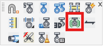
Create 3D Seismic Braces
Layer(s): HCAD-3d_Hangers
Shortcut: 3DS
Seismic Braces can be added to the system separate from ‘regular’ hangers. When adding seismic bracing it is assumed that the 3D model has been made at least once. Seismic braces are added while the drawing is in 2D mode (Edit Mode).
Top of Structure Deflines must be inserted in the drawing for seismic braces to be added. This will determine the elevation between the pipe and top of steel or bottom of structure.
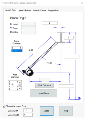
Set the type of brace by picking the tabs at top.
The Pick Distance button to set the distance between the pipe to be braced and the structure member to attach to.
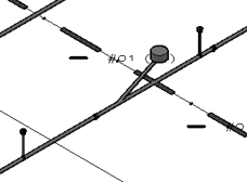
Select along the pipe where you want the brace to be located. Then, Select the other end of the brace. This is the connection point to the structure.
Information about the pipe picked and top of steel will be entered into the dialog box.
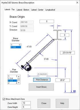
If required, enter the desired offsets for attaching the top of the brace to the bottom and side of a structural beam. The default Brace Diameter is 1¼”. If required, change it to 1”.
Show Attachment Zone draws a circular area around the top of the brace where it attaches to the structure. It is used during the BIM process to clear the area for hanger inserts. Adjust dimensions as needed. This is often not required when attaching to steel beams and can be turned off by unchecking the Show Attachment Zone check box.
Once the brace description is complete, pick the Insert Brace button to insert the brace into the drawing.
Go to 3D to view these hangers and pipes.
HydraCARDs (Troubleshooting)
For HydraCARDs regarding Create 3D Seismic Braces: [Click Here]