Appearance
Pipe and Fitting Direction
This section provides instructions on how to install pipe, valves and fittings and control their direction.
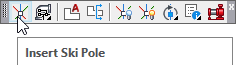
Start the Insert Ski Pole command by selecting it from the Build 3D Risers toolbar.

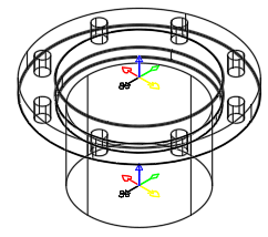
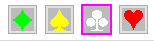
The Ski Pole is a directional reference for your 3D drawing. There are five color-coded symbols on it. Use these symbols to insert 3D components with your first and subsequent connections. The blue spear symbol in the center indicates the direction in which the new item will be placed. The red heart, white club, yellow spade and green diamond symbols determine the orientation of the item.
You must have a Ski Pole inserted first before inserting the first component. Subsequent items will already have Ski Poles at connection points. Use the mouse to pick the location of the first Ski Pole. Ski Poles are very small when inserted. You will have to zoom in very close to see them.
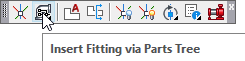
Press Insert Fitting via Parts Tree to start the command.
The Insert Fittings dialog box will appear.

Select the Pipes tab.
End Prep1 will be Plain End. Diameter will be 6”. End prep 2 will be Flanged.
The Length will be 6”.
Press Insert Pipe.
Pick the existing ski pole.
The pipe is inserted. The Insert Fittings dialog box will return.
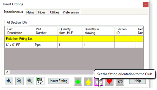
Pick the Miscellaneous tab and press the Club symbol.
Also found in the Miscellaneous window are four color coded Ski Pole symbols. These symbols determine the direction when inserting new components.
For example, when inserting an elbow on a flanged pipe, view the Ski Pole to determine the direction.
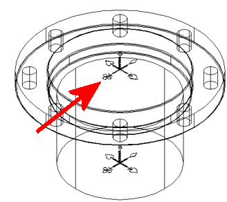
If the white club symbol is selected, the open end of the elbow will be in the same direction.
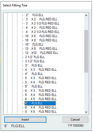
Select a Flanged Fittings > 90 Elbow > 90 > 6” FLG ELL. Press Insert.
You will return to the drawing. Pick anywhere on the Ski Pole.
Where you pick on the Ski Pole is irrelevant because you have already determined the orientation of the elbow in the Insert Fittings dialog box.
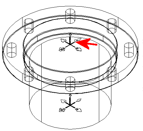
The flanged elbow is inserted in the specified direction.
If you insert a component in the wrong position you can resolve the problem in one of three ways.
Press the AutoCAD undo command.
Close the Insert Fittings dialog box, then pick and delete the item and start over
Or, you can rotate the item.
There is also an Undo button located on the Miscellaneous window for quick access.